Gesture Controlled Car with Accelerometer
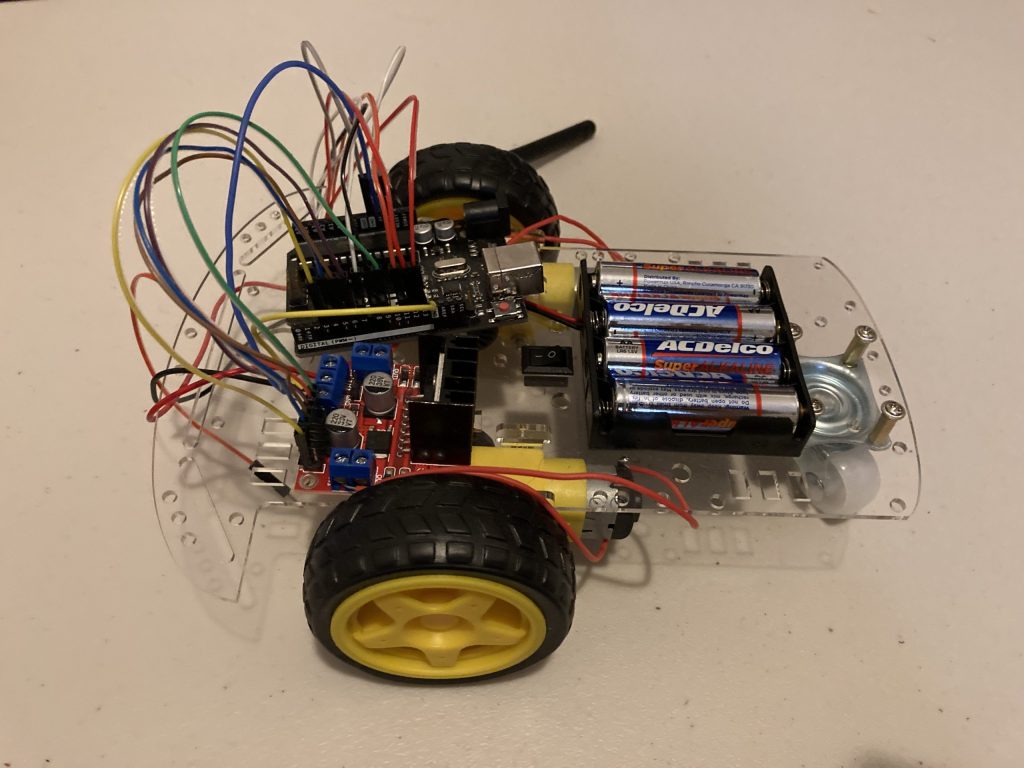
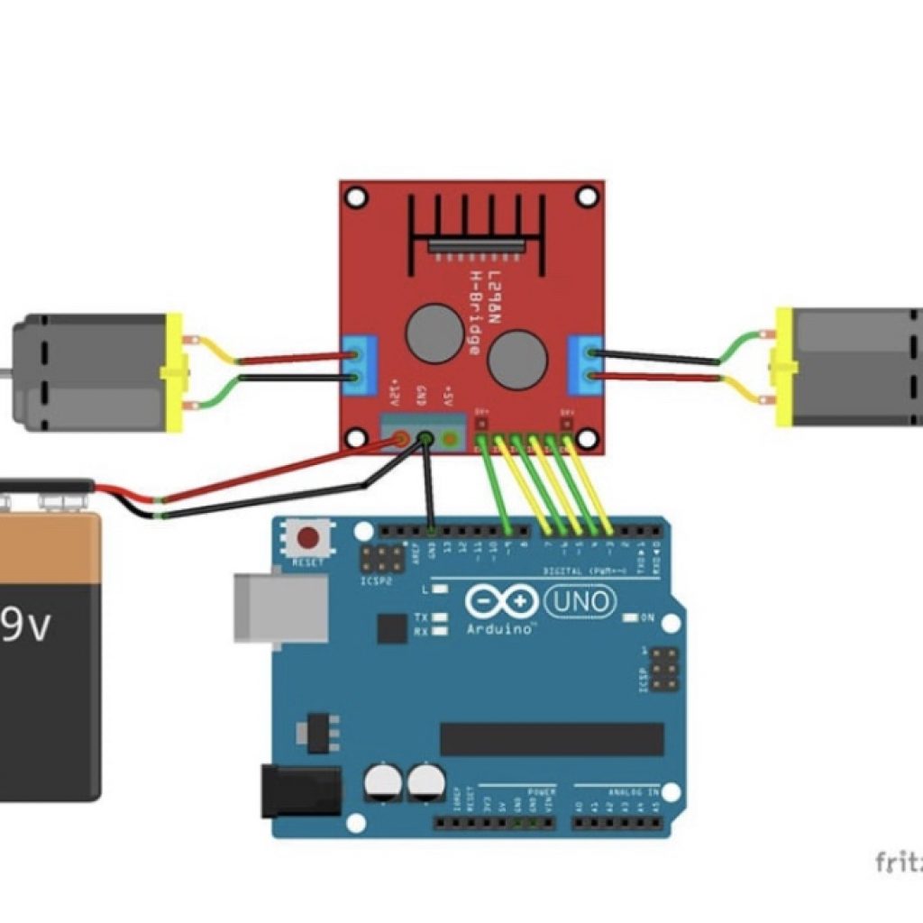
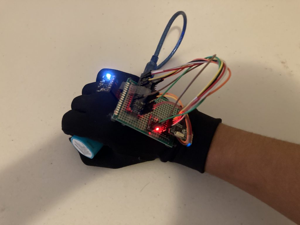
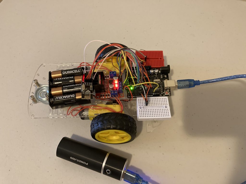
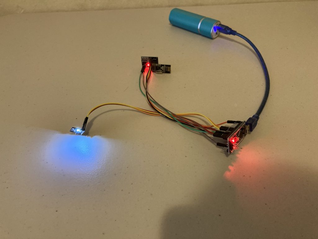
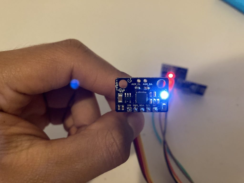
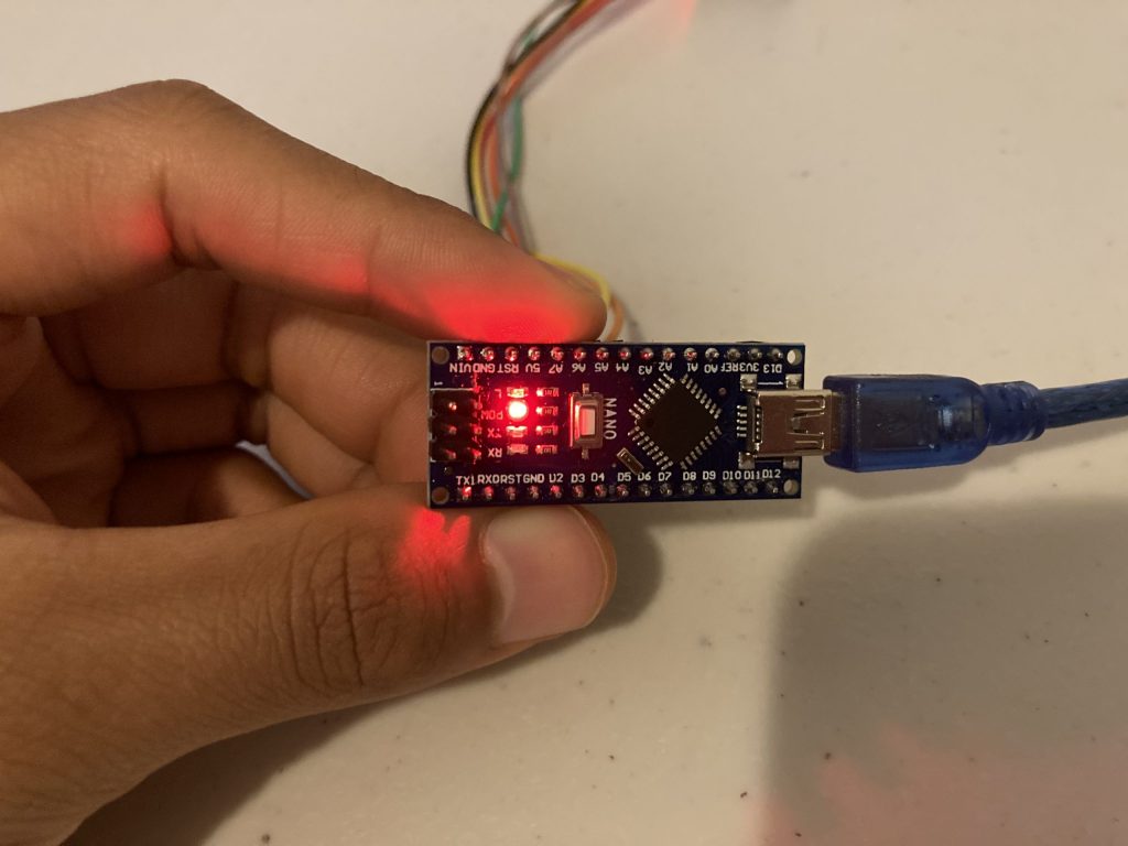
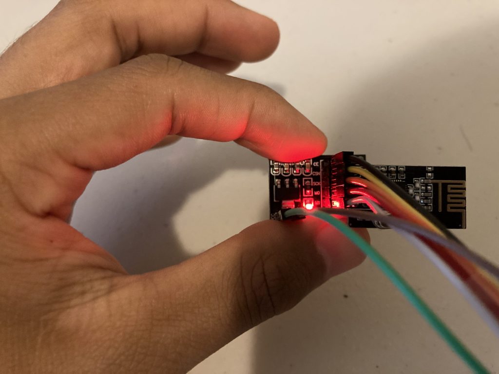
My project is the gesture controlled car with an accelerometer. This project incorporates the unique functions of the Arduino Uno and Arduino Nano with other devices such as a motor driver, an accelerometer, and NRF modules in order to perform impressive tasks. In this project the following components work together so that specific hand motions can be interpreted as commands for my robot car to move in a set direction.
Engineer
Fernando Rodriguez Leal
Area of Interest
Electrical/ Aerospace Engineering
School
NYC iSchool
Grade
Incoming Senior
Reflection
#include <SPI.h>
#include <nRF24L01.h>
#include <RF24.h>
#include <Adafruit_MPU6050.h>
#include <Adafruit_Sensor.h>
#include <Wire.h>
#include <L298N.h>
#include <Adafruit_NeoPixel.h>
#define LED_PIN 2
#define LED_COUNT 36
// Declare our NeoPixel strip object:
Adafruit_NeoPixel strip(LED_COUNT, LED_PIN, NEO_GRB + NEO_KHZ800);
const unsigned int IN1 = 10;
const unsigned int IN2 = 6;
const unsigned int ENA = 9;
const unsigned int IN3 = 5;
const unsigned int IN4 = 4;
const unsigned int ENB = 3;
RF24 radio(7,8); // CE, CSN
int value = -1;
const byte address[6] = “00001”;
Adafruit_MPU6050 mpu;
void setup() {
Serial.begin(9600);
radio.begin();
radio.openReadingPipe(0, address);
radio.setPALevel(RF24_PA_MIN);
radio.startListening();
pinMode (IN1, OUTPUT);
pinMode (IN2, OUTPUT);
pinMode (IN3, OUTPUT);
pinMode (IN4, OUTPUT);
pinMode (ENA, OUTPUT);
pinMode (ENB, OUTPUT);
delay(100);
strip.begin();
strip.show(); // Initialize all pixels to ‘off’
}
void loop() {
if (radio.available()) {
radio.read(&value, sizeof(value));
Serial.println(value);
if (value == 2) {
//Serial.print(text);
analogWrite(ENA, 255);
analogWrite(ENB, 255);
digitalWrite(IN1, HIGH);
digitalWrite(IN2, LOW);
digitalWrite(IN3, LOW);
digitalWrite(IN4, HIGH);
for (int n = 0; n < LED_COUNT; n++)
{
strip.setPixelColor(n, 251, 255, 5); //set pixel color to be yellow
}
strip.show();
}
else if (value == 3) {
analogWrite(ENA, 255);
analogWrite(ENB, 255);
digitalWrite(IN1, LOW);
digitalWrite(IN2, HIGH);
digitalWrite(IN3, HIGH);
digitalWrite(IN4, LOW);
for (int n = 0; n < LED_COUNT; n++)
{
strip.setPixelColor(n, 26, 127, 235); //set pixel color to be blue
}
strip.show();
}
else if (value == 0) {
analogWrite(ENA, 255);
analogWrite(ENB, 255);
digitalWrite(IN1, LOW);
digitalWrite(IN2, HIGH);
digitalWrite(IN3, LOW);
digitalWrite(IN4, HIGH);
for (int n = 0; n < LED_COUNT; n++)
{
strip.setPixelColor(n, 0, 200, 0); //set pixel color to be green
}
strip.show();
}
else if (value == 1) {
analogWrite(ENA, 255);
analogWrite(ENB, 255);
digitalWrite(IN1, HIGH);
digitalWrite(IN2, LOW);
digitalWrite(IN3, HIGH);
digitalWrite(IN4, LOW);
for (int n = 0; n < LED_COUNT; n++)
{
strip.setPixelColor(n, 235, 155, 26); //set pixel color to be orange
}
strip.show();
}
else if (value == 4) {
analogWrite(ENA, 0);
analogWrite(ENB, 0);
digitalWrite(IN1, LOW);
digitalWrite(IN2, LOW);
digitalWrite(IN3, LOW);
digitalWrite(IN4, LOW);
for (int n = 0; n < LED_COUNT; n++)
{
strip.setPixelColor(n, 200, 0, 0); //set pixel color to be red
}
strip.show();
}
else {
analogWrite(ENA, 0);
analogWrite(ENB, 0);
digitalWrite(IN1, LOW);
digitalWrite(IN2, LOW);
digitalWrite(IN3, LOW);
digitalWrite(IN4, LOW);
//digitalWrite(10, LOW);
delay(2000);
}
}
}
#include <SPI.h>
#include <nRF24L01.h>
#include <RF24.h>
#include <Adafruit_MPU6050.h>
#include <Adafruit_Sensor.h>
#include <Wire.h>
int command = -1;//0=foward
//1=backwards
//2=right
//3=left
RF24 radio(7, 8); // CE, CSN
const byte address[6] = “00001”;
Adafruit_MPU6050 mpu;
void setup() {
Serial.begin(115200);
while (!Serial)
delay(10); // will pause Zero, Leonardo, etc until serial console opens
Serial.println(“Adafruit MPU6050 test!”);
// Try to initialize!
if (!mpu.begin()) {
Serial.println(“Failed to find MPU6050 chip”);
while (1) {
delay(10);
}
}
Serial.println(“MPU6050 Found!”);
radio.begin();
radio.openWritingPipe(address);
radio.setPALevel(RF24_PA_MIN);
radio.stopListening();
mpu.setAccelerometerRange(MPU6050_RANGE_8_G);
Serial.print(“Accelerometer range set to: “);
switch (mpu.getAccelerometerRange()) {
case MPU6050_RANGE_2_G:
Serial.println(“+-2G”);
break;
case MPU6050_RANGE_4_G:
Serial.println(“+-4G”);
break;
case MPU6050_RANGE_8_G:
Serial.println(“+-8G”);
break;
case MPU6050_RANGE_16_G:
Serial.println(“+-16G”);
break;
}
mpu.setGyroRange(MPU6050_RANGE_500_DEG);
Serial.print(“Gyro range set to: “);
switch (mpu.getGyroRange()) {
case MPU6050_RANGE_250_DEG:
Serial.println(“+- 250 deg/s”);
break;
case MPU6050_RANGE_500_DEG:
Serial.println(“+- 500 deg/s”);
break;
case MPU6050_RANGE_1000_DEG:
Serial.println(“+- 1000 deg/s”);
break;
case MPU6050_RANGE_2000_DEG:
Serial.println(“+- 2000 deg/s”);
break;
}
mpu.setFilterBandwidth(MPU6050_BAND_21_HZ);
Serial.print(“Filter bandwidth set to: “);
switch (mpu.getFilterBandwidth()) {
case MPU6050_BAND_260_HZ:
Serial.println(“260 Hz”);
break;
case MPU6050_BAND_184_HZ:
Serial.println(“184 Hz”);
break;
case MPU6050_BAND_94_HZ:
Serial.println(“94 Hz”);
break;
case MPU6050_BAND_44_HZ:
Serial.println(“44 Hz”);
break;
case MPU6050_BAND_21_HZ:
Serial.println(“21 Hz”);
break;
case MPU6050_BAND_10_HZ:
Serial.println(“10 Hz”);
break;
case MPU6050_BAND_5_HZ:
Serial.println(“5 Hz”);
break;
}
Serial.println(“”);
delay(100);
}
void loop() {
sensors_event_t a, g, temp;
mpu.getEvent(&a, &g, &temp);
Serial.print(a.acceleration.x);
Serial.print(” “);
Serial.println(a.acceleration.y);
delay(250);
if (a.acceleration.x < -3) {
command = 2;
Serial.println(command);
radio.write(&command, sizeof(command));
}
else if (a.acceleration.x > 3) {
command = 3;
Serial.println(command);
radio.write(&command, sizeof(command));
}
else if (a.acceleration.y < -3) {
command = 0;
Serial.println(command);
radio.write(&command, sizeof(command));
}
else if (a.acceleration.y > 3) {
command = 1;
Serial.println(command);
radio.write(&command, sizeof(command));
}
else if (-3 < a.acceleration.y && a.acceleration.x < 3) {
command = 4;
Serial.println(command);
radio.write(&command, sizeof(command));
}
}
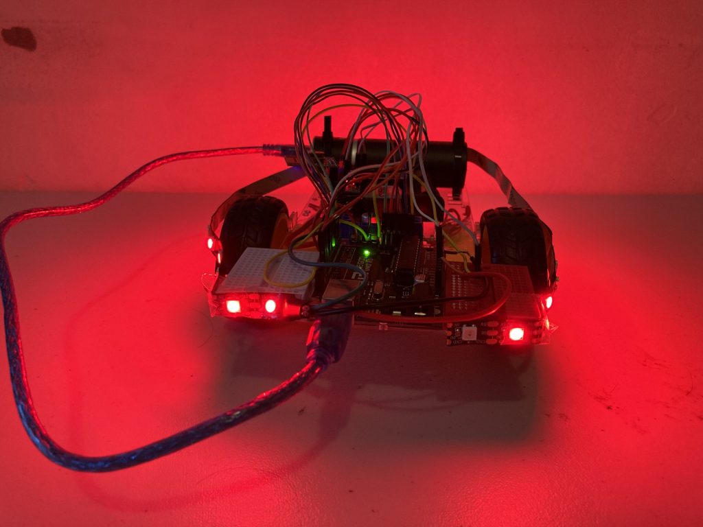
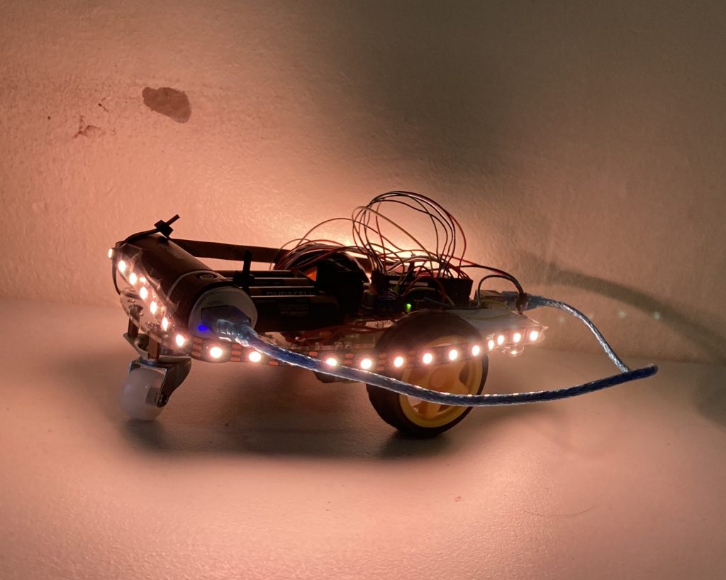
Final Milestone
#include <SPI.h>
#include <nRF24L01.h>
#include <RF24.h>
#include <Adafruit_MPU6050.h>
#include <Adafruit_Sensor.h>
#include <Wire.h>
#include <L298N.h>
#include <Adafruit_NeoPixel.h>
#define LED_PIN 2
#define LED_COUNT 36
// Declare our NeoPixel strip object:
Adafruit_NeoPixel strip(LED_COUNT, LED_PIN, NEO_GRB + NEO_KHZ800);
const unsigned int IN1 = 10;
const unsigned int IN2 = 6;
const unsigned int ENA = 9;
const unsigned int IN3 = 5;
const unsigned int IN4 = 4;
const unsigned int ENB = 3;
RF24 radio(7,8); // CE, CSN
int value = -1;
const byte address[6] = “00001”;
Adafruit_MPU6050 mpu;
void setup() {
Serial.begin(9600);
radio.begin();
radio.openReadingPipe(0, address);
radio.setPALevel(RF24_PA_MIN);
radio.startListening();
pinMode (IN1, OUTPUT);
pinMode (IN2, OUTPUT);
pinMode (IN3, OUTPUT);
pinMode (IN4, OUTPUT);
pinMode (ENA, OUTPUT);
pinMode (ENB, OUTPUT);
delay(100);
strip.begin();
strip.show(); // Initialize all pixels to ‘off’
}
void loop() {
if (radio.available()) {
radio.read(&value, sizeof(value));
Serial.println(value);
if (value == 2) {
//Serial.print(text);
analogWrite(ENA, 255);
analogWrite(ENB, 255);
digitalWrite(IN1, HIGH);
digitalWrite(IN2, LOW);
digitalWrite(IN3, LOW);
digitalWrite(IN4, HIGH);
for (int n = 0; n < LED_COUNT; n++)
{
strip.setPixelColor(n, 251, 255, 5); //set pixel color to be yellow
}
strip.show();
}
else if (value == 3) {
analogWrite(ENA, 255);
analogWrite(ENB, 255);
digitalWrite(IN1, LOW);
digitalWrite(IN2, HIGH);
digitalWrite(IN3, HIGH);
digitalWrite(IN4, LOW);
for (int n = 0; n < LED_COUNT; n++)
{
strip.setPixelColor(n, 26, 127, 235); //set pixel color to be blue
}
strip.show();
}
else if (value == 0) {
analogWrite(ENA, 255);
analogWrite(ENB, 255);
digitalWrite(IN1, LOW);
digitalWrite(IN2, HIGH);
digitalWrite(IN3, LOW);
digitalWrite(IN4, HIGH);
for (int n = 0; n < LED_COUNT; n++)
{
strip.setPixelColor(n, 0, 200, 0); //set pixel color to be green
}
strip.show();
}
else if (value == 1) {
analogWrite(ENA, 255);
analogWrite(ENB, 255);
digitalWrite(IN1, HIGH);
digitalWrite(IN2, LOW);
digitalWrite(IN3, HIGH);
digitalWrite(IN4, LOW);
for (int n = 0; n < LED_COUNT; n++)
{
strip.setPixelColor(n, 235, 155, 26); //set pixel color to be orange
}
strip.show();
}
else if (value == 4) {
analogWrite(ENA, 0);
analogWrite(ENB, 0);
digitalWrite(IN1, LOW);
digitalWrite(IN2, LOW);
digitalWrite(IN3, LOW);
digitalWrite(IN4, LOW);
for (int n = 0; n < LED_COUNT; n++)
{
strip.setPixelColor(n, 200, 0, 0); //set pixel color to be red
}
strip.show();
}
else {
analogWrite(ENA, 0);
analogWrite(ENB, 0);
digitalWrite(IN1, LOW);
digitalWrite(IN2, LOW);
digitalWrite(IN3, LOW);
digitalWrite(IN4, LOW);
//digitalWrite(10, LOW);
delay(2000);
}
}
}
#include <SPI.h>
#include <nRF24L01.h>
#include <RF24.h>
#include <Adafruit_MPU6050.h>
#include <Adafruit_Sensor.h>
#include <Wire.h>
int command = -1;//0=foward
//1=backwards
//2=right
//3=left
RF24 radio(7, 8); // CE, CSN
const byte address[6] = “00001”;
Adafruit_MPU6050 mpu;
void setup() {
Serial.begin(115200);
while (!Serial)
delay(10); // will pause Zero, Leonardo, etc until serial console opens
Serial.println(“Adafruit MPU6050 test!”);
// Try to initialize!
if (!mpu.begin()) {
Serial.println(“Failed to find MPU6050 chip”);
while (1) {
delay(10);
}
}
Serial.println(“MPU6050 Found!”);
radio.begin();
radio.openWritingPipe(address);
radio.setPALevel(RF24_PA_MIN);
radio.stopListening();
mpu.setAccelerometerRange(MPU6050_RANGE_8_G);
Serial.print(“Accelerometer range set to: “);
switch (mpu.getAccelerometerRange()) {
case MPU6050_RANGE_2_G:
Serial.println(“+-2G”);
break;
case MPU6050_RANGE_4_G:
Serial.println(“+-4G”);
break;
case MPU6050_RANGE_8_G:
Serial.println(“+-8G”);
break;
case MPU6050_RANGE_16_G:
Serial.println(“+-16G”);
break;
}
mpu.setGyroRange(MPU6050_RANGE_500_DEG);
Serial.print(“Gyro range set to: “);
switch (mpu.getGyroRange()) {
case MPU6050_RANGE_250_DEG:
Serial.println(“+- 250 deg/s”);
break;
case MPU6050_RANGE_500_DEG:
Serial.println(“+- 500 deg/s”);
break;
case MPU6050_RANGE_1000_DEG:
Serial.println(“+- 1000 deg/s”);
break;
case MPU6050_RANGE_2000_DEG:
Serial.println(“+- 2000 deg/s”);
break;
}
mpu.setFilterBandwidth(MPU6050_BAND_21_HZ);
Serial.print(“Filter bandwidth set to: “);
switch (mpu.getFilterBandwidth()) {
case MPU6050_BAND_260_HZ:
Serial.println(“260 Hz”);
break;
case MPU6050_BAND_184_HZ:
Serial.println(“184 Hz”);
break;
case MPU6050_BAND_94_HZ:
Serial.println(“94 Hz”);
break;
case MPU6050_BAND_44_HZ:
Serial.println(“44 Hz”);
break;
case MPU6050_BAND_21_HZ:
Serial.println(“21 Hz”);
break;
case MPU6050_BAND_10_HZ:
Serial.println(“10 Hz”);
break;
case MPU6050_BAND_5_HZ:
Serial.println(“5 Hz”);
break;
}
Serial.println(“”);
delay(100);
}
void loop() {
sensors_event_t a, g, temp;
mpu.getEvent(&a, &g, &temp);
Serial.print(a.acceleration.x);
Serial.print(” “);
Serial.println(a.acceleration.y);
delay(250);
if (a.acceleration.x < -3) {
command = 2;
Serial.println(command);
radio.write(&command, sizeof(command));
}
else if (a.acceleration.x > 3) {
command = 3;
Serial.println(command);
radio.write(&command, sizeof(command));
}
else if (a.acceleration.y < -3) {
command = 0;
Serial.println(command);
radio.write(&command, sizeof(command));
}
else if (a.acceleration.y > 3) {
command = 1;
Serial.println(command);
radio.write(&command, sizeof(command));
}
else if (-3 < a.acceleration.y && a.acceleration.x < 3) {
command = 4;
Serial.println(command);
radio.write(&command, sizeof(command));
}
}
Third Milestone
#include <SPI.h>
#include <nRF24L01.h>
#include <RF24.h>
#include <Adafruit_MPU6050.h>
#include <Adafruit_Sensor.h>
#include <Wire.h>
int command = -1;//0=foward
//1=backwards
//2=right
//3=left
RF24 radio(7, 8); // CE, CSN
const byte address[6] = “00001”;
Adafruit_MPU6050 mpu;
void setup() {
Serial.begin(115200);
while (!Serial)
delay(10); // will pause Zero, Leonardo, etc until serial console opens
Serial.println(“Adafruit MPU6050 test!”);
// Try to initialize!
if (!mpu.begin()) {
Serial.println(“Failed to find MPU6050 chip”);
while (1) {
delay(10);
}
}
Serial.println(“MPU6050 Found!”);
radio.begin();
radio.openWritingPipe(address);
radio.setPALevel(RF24_PA_MIN);
radio.stopListening();
mpu.setAccelerometerRange(MPU6050_RANGE_8_G);
Serial.print(“Accelerometer range set to: “);
switch (mpu.getAccelerometerRange()) {
case MPU6050_RANGE_2_G:
Serial.println(“+-2G”);
break;
case MPU6050_RANGE_4_G:
Serial.println(“+-4G”);
break;
case MPU6050_RANGE_8_G:
Serial.println(“+-8G”);
break;
case MPU6050_RANGE_16_G:
Serial.println(“+-16G”);
break;
}
mpu.setGyroRange(MPU6050_RANGE_500_DEG);
Serial.print(“Gyro range set to: “);
switch (mpu.getGyroRange()) {
case MPU6050_RANGE_250_DEG:
Serial.println(“+- 250 deg/s”);
break;
case MPU6050_RANGE_500_DEG:
Serial.println(“+- 500 deg/s”);
break;
case MPU6050_RANGE_1000_DEG:
Serial.println(“+- 1000 deg/s”);
break;
case MPU6050_RANGE_2000_DEG:
Serial.println(“+- 2000 deg/s”);
break;
}
mpu.setFilterBandwidth(MPU6050_BAND_21_HZ);
Serial.print(“Filter bandwidth set to: “);
switch (mpu.getFilterBandwidth()) {
case MPU6050_BAND_260_HZ:
Serial.println(“260 Hz”);
break;
case MPU6050_BAND_184_HZ:
Serial.println(“184 Hz”);
break;
case MPU6050_BAND_94_HZ:
Serial.println(“94 Hz”);
break;
case MPU6050_BAND_44_HZ:
Serial.println(“44 Hz”);
break;
case MPU6050_BAND_21_HZ:
Serial.println(“21 Hz”);
break;
case MPU6050_BAND_10_HZ:
Serial.println(“10 Hz”);
break;
case MPU6050_BAND_5_HZ:
Serial.println(“5 Hz”);
break;
}
Serial.println(“”);
delay(100);
}
void loop() {
sensors_event_t a, g, temp;
mpu.getEvent(&a, &g, &temp);
Serial.print(a.acceleration.x);
Serial.print(” “);
Serial.println(a.acceleration.y);
delay(250);
if (a.acceleration.x < -3) {
command = 2;
Serial.println(command);
radio.write(&command, sizeof(command));
}
else if (a.acceleration.x > 3) {
command = 3;
Serial.println(command);
radio.write(&command, sizeof(command));
}
else if (a.acceleration.y < -3) {
command = 0;
Serial.println(command);
radio.write(&command, sizeof(command));
}
else if (a.acceleration.y > 3) {
command = 1;
Serial.println(command);
radio.write(&command, sizeof(command));
}
else if (-3 < a.acceleration.y && a.acceleration.x < 3) {
command = 4;
Serial.println(command);
radio.write(&command, sizeof(command));
}
}
#include <SPI.h>
#include <nRF24L01.h>
#include <RF24.h>
#include <Adafruit_MPU6050.h>
#include <Adafruit_Sensor.h>
#include <Wire.h>
#include <L298N.h>
const unsigned int IN1 = 10;
const unsigned int IN2 = 6;
const unsigned int ENA = 9;
const unsigned int IN3 = 5;
const unsigned int IN4 = 4;
const unsigned int ENB = 3;
RF24 radio(7,8); // CE, CSN
int value = -1;
const byte address[6] = “00001”;
Adafruit_MPU6050 mpu;
void setup() {
Serial.begin(9600);
radio.begin();
radio.openReadingPipe(0, address);
radio.setPALevel(RF24_PA_MIN);
radio.startListening();
pinMode (IN1, OUTPUT);
pinMode (IN2, OUTPUT);
pinMode (IN3, OUTPUT);
pinMode (IN4, OUTPUT);
pinMode (ENA, OUTPUT);
pinMode (ENB, OUTPUT);
delay(100);
}
void loop() {
if (radio.available()) {
radio.read(&value, sizeof(value));
Serial.println(value);
if (value == 2) {
//Serial.print(text);
analogWrite(ENA, 255);
analogWrite(ENB, 255);
digitalWrite(IN1, HIGH);
digitalWrite(IN2, LOW);
digitalWrite(IN3, LOW);
digitalWrite(IN4, HIGH);
}
else if (value == 3) {
analogWrite(ENA, 255);
analogWrite(ENB, 255);
digitalWrite(IN1, LOW);
digitalWrite(IN2, HIGH);
digitalWrite(IN3, HIGH);
digitalWrite(IN4, LOW);
}
else if (value == 0) {
analogWrite(ENA, 255);
analogWrite(ENB, 255);
digitalWrite(IN1, LOW);
digitalWrite(IN2, HIGH);
digitalWrite(IN3, LOW);
digitalWrite(IN4, HIGH);
}
else if (value == 1) {
analogWrite(ENA, 255);
analogWrite(ENB, 255);
digitalWrite(IN1, HIGH);
digitalWrite(IN2, LOW);
digitalWrite(IN3, HIGH);
digitalWrite(IN4, LOW);
}
else if (value == 4) {
analogWrite(ENA, 0);
analogWrite(ENB, 0);
digitalWrite(IN1, LOW);
digitalWrite(IN2, LOW);
digitalWrite(IN3, LOW);
digitalWrite(IN4, LOW);
}
else {
analogWrite(ENA, 0);
analogWrite(ENB, 0);
digitalWrite(IN1, LOW);
digitalWrite(IN2, LOW);
digitalWrite(IN3, LOW);
digitalWrite(IN4, LOW);
//digitalWrite(10, LOW);
delay(2000);
}
}
}
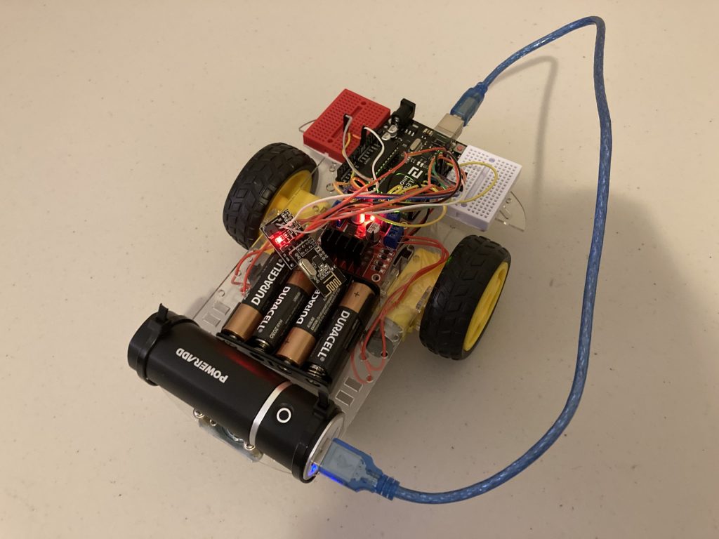
Second Milestone
/*
Arduino and MPU6050 Accelerometer and Gyroscope Sensor Tutorial
by Dejan, https://howtomechatronics.com
*/
#include <Wire.h>
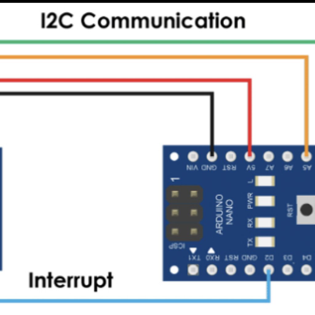
const int MPU = 0x68; // MPU6050 I2C address
float AccX, AccY, AccZ;
float GyroX, GyroY, GyroZ;
float accAngleX, accAngleY, gyroAngleX, gyroAngleY, gyroAngleZ;
float roll, pitch, yaw;
float AccErrorX, AccErrorY, GyroErrorX, GyroErrorY, GyroErrorZ;
float elapsedTime, currentTime, previousTime;
int c = 0;
void setup() {
Serial.begin(19200);
Wire.begin(); // Initialize comunication
Wire.beginTransmission(MPU); // Start communication with MPU6050 // MPU=0x68
Wire.write(0x6B); // Talk to the register 6B
Wire.write(0x00); // Make reset - place a 0 into the 6B register
Wire.endTransmission(true); //end the transmission
/*
// Configure Accelerometer Sensitivity - Full Scale Range (default +/- 2g)
Wire.beginTransmission(MPU);
Wire.write(0x1C); //Talk to the ACCEL_CONFIG register (1C hex)
Wire.write(0x10); //Set the register bits as 00010000 (+/- 8g full scale range)
Wire.endTransmission(true);
// Configure Gyro Sensitivity - Full Scale Range (default +/- 250deg/s)
Wire.beginTransmission(MPU);
Wire.write(0x1B); // Talk to the GYRO_CONFIG register (1B hex)
Wire.write(0x10); // Set the register bits as 00010000 (1000deg/s full scale)
Wire.endTransmission(true);
delay(20);
*/
// Call this function if you need to get the IMU error values for your module
calculate_IMU_error();
delay(20);
}
void loop() {
// === Read acceleromter data === //
Wire.beginTransmission(MPU);
Wire.write(0x3B); // Start with register 0x3B (ACCEL_XOUT_H)
Wire.endTransmission(false);
Wire.requestFrom(MPU, 6, true); // Read 6 registers total, each axis value is stored in 2 registers
//For a range of +-2g, we need to divide the raw values by 16384, according to the datasheet
AccX = (Wire.read() << 8 | Wire.read()) / 16384.0; // X-axis value
AccY = (Wire.read() << 8 | Wire.read()) / 16384.0; // Y-axis value
AccZ = (Wire.read() << 8 | Wire.read()) / 16384.0; // Z-axis value
// Calculating Roll and Pitch from the accelerometer data
accAngleX = (atan(AccY / sqrt(pow(AccX, 2) + pow(AccZ, 2))) * 180 / PI) - 0.58; // AccErrorX ~(0.58) See the calculate_IMU_error()custom function for more details
accAngleY = (atan(-1 * AccX / sqrt(pow(AccY, 2) + pow(AccZ, 2))) * 180 / PI) + 1.58; // AccErrorY ~(-1.58)
// === Read gyroscope data === //
previousTime = currentTime; // Previous time is stored before the actual time read
currentTime = millis(); // Current time actual time read
elapsedTime = (currentTime - previousTime) / 1000; // Divide by 1000 to get seconds
Wire.beginTransmission(MPU);
Wire.write(0x43); // Gyro data first register address 0x43
Wire.endTransmission(false);
Wire.requestFrom(MPU, 6, true); // Read 4 registers total, each axis value is stored in 2 registers
GyroX = (Wire.read() << 8 | Wire.read()) / 131.0; // For a 250deg/s range we have to divide first the raw value by 131.0, according to the datasheet
GyroY = (Wire.read() << 8 | Wire.read()) / 131.0;
GyroZ = (Wire.read() << 8 | Wire.read()) / 131.0;
// Correct the outputs with the calculated error values
GyroX = GyroX + 0.56; // GyroErrorX ~(-0.56)
GyroY = GyroY - 2; // GyroErrorY ~(2)
GyroZ = GyroZ + 0.79; // GyroErrorZ ~ (-0.8)
// Currently the raw values are in degrees per seconds, deg/s, so we need to multiply by sendonds (s) to get the angle in degrees
gyroAngleX = gyroAngleX + GyroX * elapsedTime; // deg/s * s = deg
gyroAngleY = gyroAngleY + GyroY * elapsedTime;
yaw = yaw + GyroZ * elapsedTime;
// Complementary filter - combine acceleromter and gyro angle values
roll = 0.96 * gyroAngleX + 0.04 * accAngleX;
pitch = 0.96 * gyroAngleY + 0.04 * accAngleY;
// Print the values on the serial monitor
Serial.print(roll);
Serial.print("/");
Serial.print(pitch);
Serial.print("/");
Serial.println(yaw);
}
void calculate_IMU_error() {
// We can call this funtion in the setup section to calculate the accelerometer and gyro data error. From here we will get the error values used in the above equations printed on the Serial Monitor.
// Note that we should place the IMU flat in order to get the proper values, so that we then can the correct values
// Read accelerometer values 200 times
while (c < 200) {
Wire.beginTransmission(MPU);
Wire.write(0x3B);
Wire.endTransmission(false);
Wire.requestFrom(MPU, 6, true);
AccX = (Wire.read() << 8 | Wire.read()) / 16384.0 ;
AccY = (Wire.read() << 8 | Wire.read()) / 16384.0 ;
AccZ = (Wire.read() << 8 | Wire.read()) / 16384.0 ;
// Sum all readings
AccErrorX = AccErrorX + ((atan((AccY) / sqrt(pow((AccX), 2) + pow((AccZ), 2))) * 180 / PI));
AccErrorY = AccErrorY + ((atan(-1 * (AccX) / sqrt(pow((AccY), 2) + pow((AccZ), 2))) * 180 / PI));
c++;
}
//Divide the sum by 200 to get the error value
AccErrorX = AccErrorX / 200;
AccErrorY = AccErrorY / 200;
c = 0;
// Read gyro values 200 times
while (c < 200) {
Wire.beginTransmission(MPU);
Wire.write(0x43);
Wire.endTransmission(false);
Wire.requestFrom(MPU, 6, true);
GyroX = Wire.read() << 8 | Wire.read();
GyroY = Wire.read() << 8 | Wire.read();
GyroZ = Wire.read() << 8 | Wire.read();
// Sum all readings
GyroErrorX = GyroErrorX + (GyroX / 131.0);
GyroErrorY = GyroErrorY + (GyroY / 131.0);
GyroErrorZ = GyroErrorZ + (GyroZ / 131.0);
c++;
}
//Divide the sum by 200 to get the error value
GyroErrorX = GyroErrorX / 200;
GyroErrorY = GyroErrorY / 200;
GyroErrorZ = GyroErrorZ / 200;
// Print the error values on the Serial Monitor
Serial.print("AccErrorX: ");
Serial.println(AccErrorX);
Serial.print("AccErrorY: ");
Serial.println(AccErrorY);
Serial.print("GyroErrorX: ");
Serial.println(GyroErrorX);
Serial.print("GyroErrorY: ");
Serial.println(GyroErrorY);
Serial.print("GyroErrorZ: ");
Serial.println(GyroErrorZ);
}
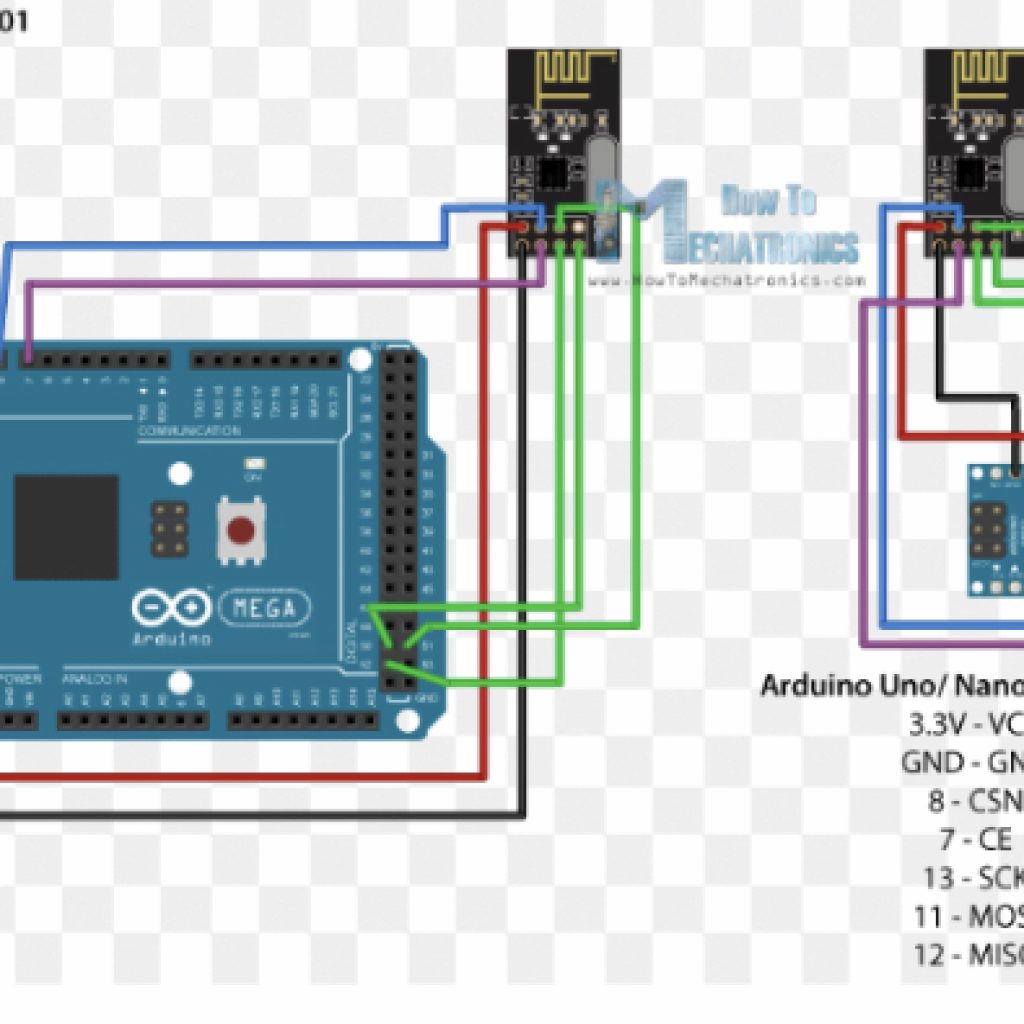
/*
* Arduino Wireless Communication Tutorial
*     Example 1 - Transmitter Code
*
* by Dejan Nedelkovski, www.HowToMechatronics.com
*
* Library: TMRh20/RF24, https://github.com/tmrh20/RF24/
*/

#include <SPI.h>
#include <nRF24L01.h>
#include <RF24.h>

RF24 radio(7, 8); // CE, CSN

const byte address[6] = "00001";

void setup() {
  radio.begin();
  radio.openWritingPipe(address);
  radio.setPALevel(RF24_PA_MIN);
  radio.stopListening();
}

void loop() {
  const char text[] = "Hello World";
  radio.write(&text, sizeof(text));
  delay(1000);
}
/*
* Arduino Wireless Communication Tutorial
*       Example 1 - Receiver Code
*
* by Dejan Nedelkovski, www.HowToMechatronics.com
*
* Library: TMRh20/RF24, https://github.com/tmrh20/RF24/
*/

#include <SPI.h>
#include <nRF24L01.h>
#include <RF24.h>

RF24 radio(7, 8); // CE, CSN

const byte address[6] = "00001";

void setup() {
  Serial.begin(9600);
  radio.begin();
  radio.openReadingPipe(0, address);
  radio.setPALevel(RF24_PA_MIN);
  radio.startListening();
}

void loop() {
  if (radio.available()) {
    char text[32] = "";
    radio.read(&text, sizeof(text));
    Serial.println(text);
  }
}
// 18 Mar 2018 – simple program to verify connection between Arduino
// and nRF24L01+
// This program does NOT attempt any communication with another nRF24
#include <SPI.h>
#include <nRF24L01.h>
#include <RF24.h>
#include <printf.h>
#define CE_PIN 9
#define CSN_PIN 10
const byte thisSlaveAddress[5] = {‘R’,’x’,’A’,’A’,’A’};
RF24 radio(CE_PIN, CSN_PIN);
char dataReceived[10]; // this must match dataToSend in the TX
bool newData = false;
void setup() {
Serial.begin(9600);
printf_begin();
Serial.println(“CheckConnection Starting”);
Serial.println();
Serial.println(“FIRST WITH THE DEFAULT ADDRESSES after power on”);
Serial.println(” Note that RF24 does NOT reset when Arduino resets – only when power is removed”);
Serial.println(” If the numbers are mostly 0x00 or 0xff it means that the Arduino is not”);
Serial.println(” communicating with the nRF24″);
Serial.println();
radio.begin();
radio.printDetails();
Serial.println();
Serial.println();
Serial.println(“AND NOW WITH ADDRESS AAAxR 0x41 41 41 78 52 ON P1″);
Serial.println(” and 250KBPS data rate”);
Serial.println();
radio.openReadingPipe(1, thisSlaveAddress);
radio.setDataRate( RF24_250KBPS );
radio.printDetails();
Serial.println();
Serial.println();
}
void loop() {
}
First Milestone