Reflection
Showcase Night
Modifications
Solar Tracking System
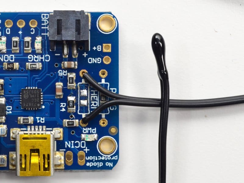
Soldering in the Thermistor
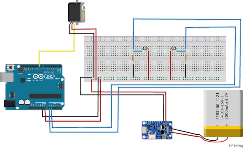
Servo Connections Schematic
My Final Milestone
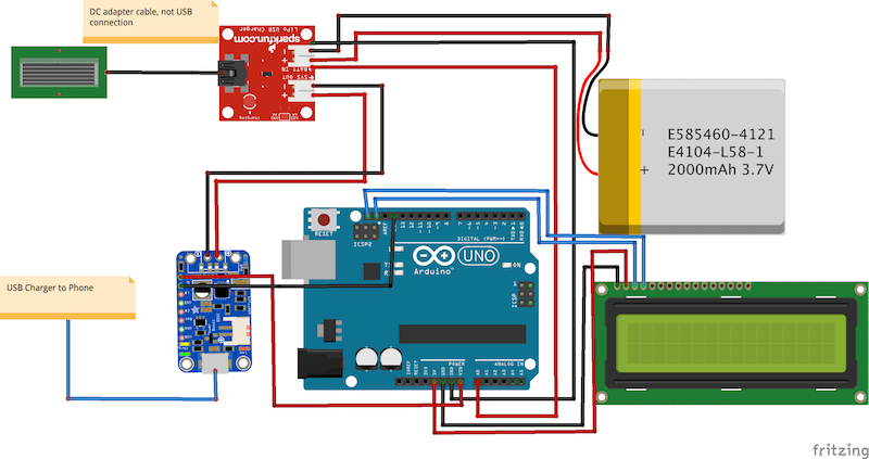
LCD and Charger Connections Schematic
Resources
My First Milestone
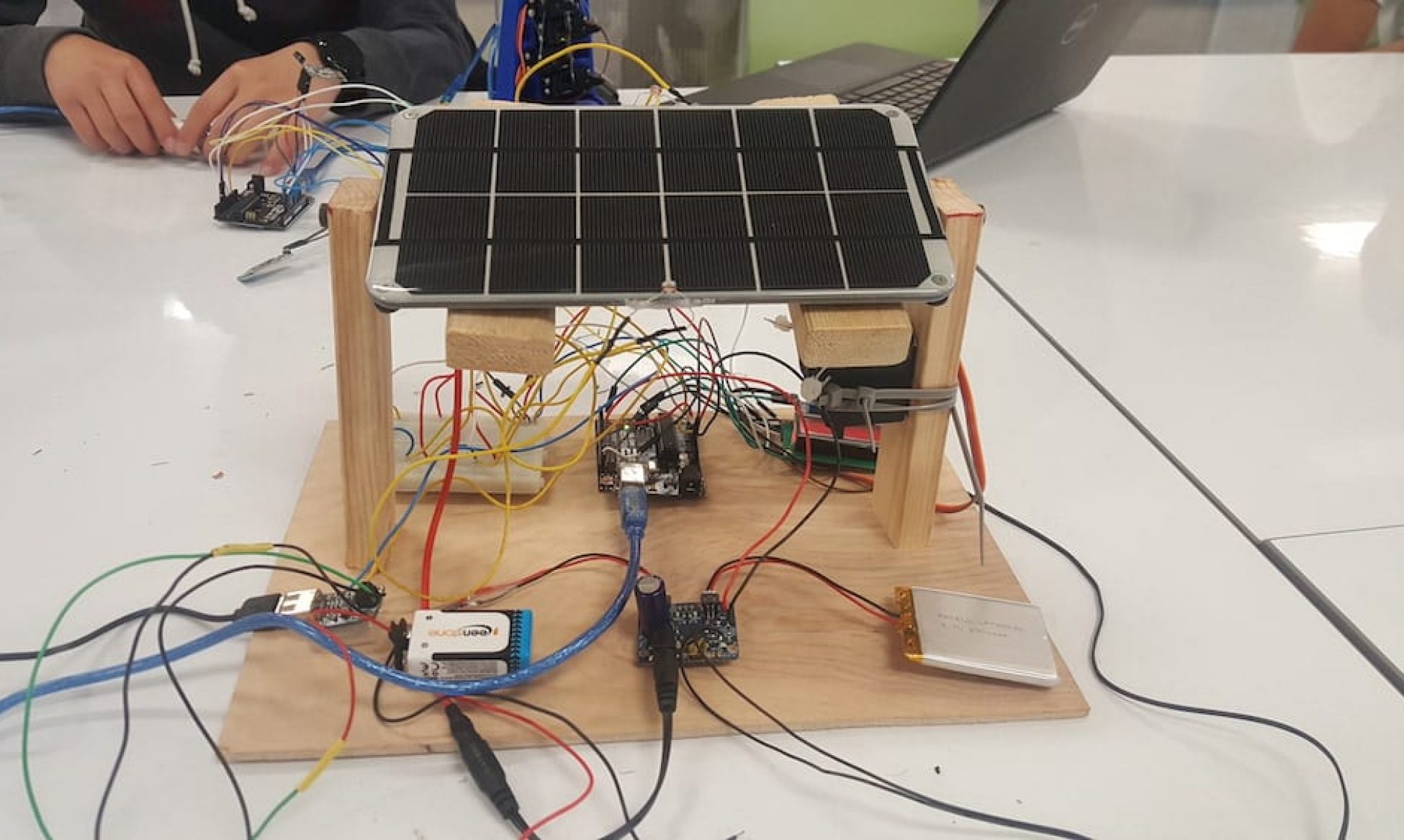
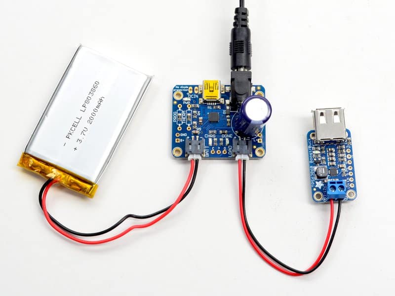
For my first milestone, I assembled the LiPo solar powered USB charger by connecting five parts: the solar panel, the LiPo charger, the LiPo battery, the AdaFruit 5v USB BuckBoost, and my phone. I needed to know how to wire circuits and how to solder. To learn how to connect everything, I had to research a lot about the different functions and connections of each part. For example, I was unaware that the solar panel required a DC adapter cable, so I had to research what type of adapter it needed in order to connect the panel to the solar LiPo charger. Also, to connect to my phone (the load), I needed a USB port and a voltage converter so I bought the BuckBoost. After I knew I had all the parts, I soldered in all the parts, which was a very easy task. I didn’t really come across any challenges, but I did need to add more solder to the capacitor since it was getting loose and bent. Overall, I’m glad I was able to assemble a working charger and learn how the chips worked with solar energy with research and a little bit of thought. For my next milestone, I will be coding Arduino to monitor and display the output voltage of the battery through an LCD display or a serial monitor. This will be difficult and require a lot of learning since I don’t have any experience with C++.

Simple Connections for LiPo Charger
Starter Project – MintyBoost
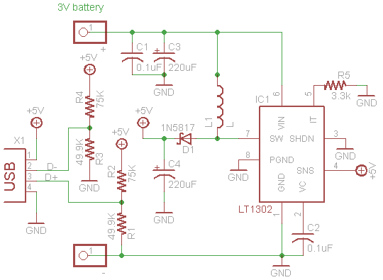
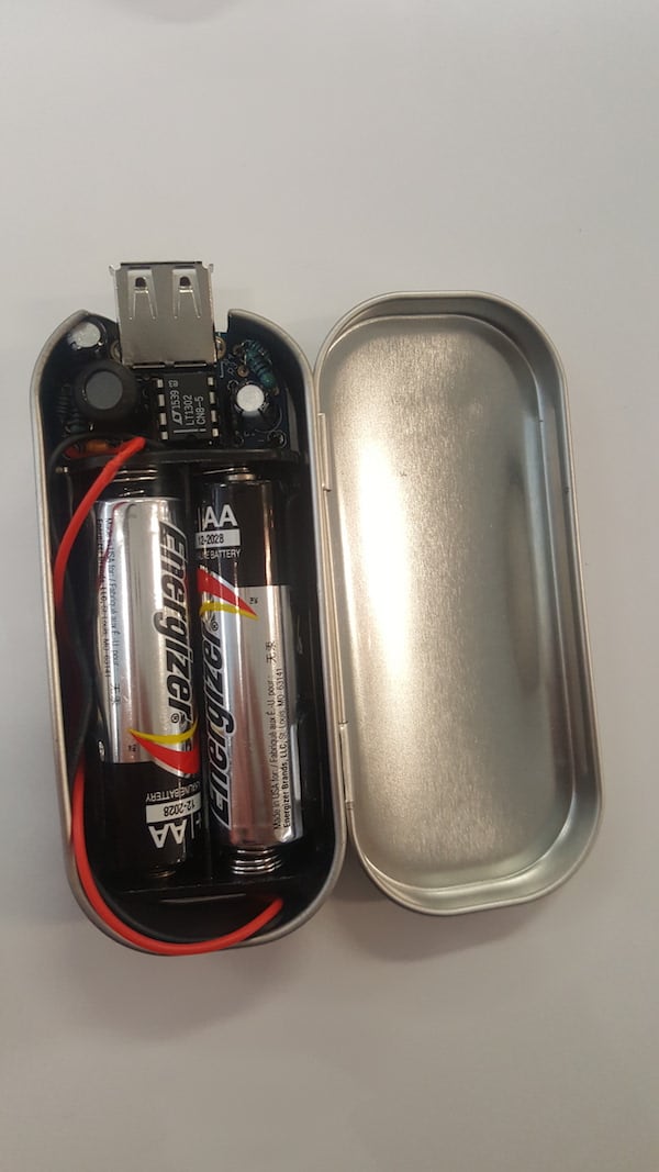
For my starter project, I decided to make the MintyBoost. The MintyBoost is a small, portable, USB phone charger which uses two AA batteries, each consisting of 1.5 volts. Coupled together, the total amount of voltage is 3 volts. This voltage goes through the printed circuit board, which consists of many different soldered components. First off, the resistors limit the flow of electrons in a circuit and there are data pins which recognize what is being charged. If resistance is too low, the MintyBoost will not work due to excessive current, according to Ohm’s Law. Next, the ceramic and electrolytic capacitors keep the voltage stable and precise in the boost converter chip. After the capacitors, the current flows into the power inductor, which is used by the boost converter chip to store and convert power from low to high. The boost converter chip converts the 3 volts from the AA batteries into 5 volts, which will make the current decrease to 0.5 amps. A major problem was only desoldering because I soldered in the wrong components into the wrong slots of the PCB. I also broke one of the resistors so instead of a 49.9K resistor, I used a 47K resistor as a replacement.


