
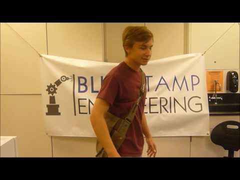
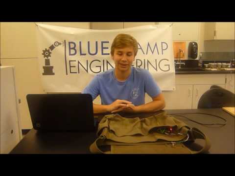
Hello my name is Ethan E and I am a rising junior at Cherry Creek High School. For my starter project I did the Mini-POV 4, which leaves a persistence of vision when you swing it back and forth, to see it in action scroll down to the video at the bottom of this page. For my intensive project I did the messenger bag that gives directions from this blog, it is able to tell the wearer information about the direction of north or a user determined way point through tactile feedback from 8 vibration motors around the bag.
Reflection
I have worked with coding a micro-controller before (lego NXT) and been part of a FIRST robotics team, but I have never gone all the way through with an individual project like this. I appreciate having a structured project with a concrete end goal to help me through the frustrations because I knew there would be something awesome at the end. Seeing it work as I planned six weeks ago is a very good feeling. I had challenges and triumphs, all of which I learned from. Specifically, one of the greatest challenges I had was a problem with the GPS that I didn’t understand for the longest time. I wasn’t getting anything from it, in the end it was the simplest problem I can imagine, a missing wire. The data wire wasn’t grounded so there was just no signal from the GPS, I learned the hard way that those small connections can’t be ignored or taken for granted. Most of the hitches I had while integrating the circuit into the bag shared the same theme, with simple overlooked short circuits. One of the richer challenges I had was calculating which motor to vibrate from GPS and compass data. I converted GPS data from characters to numbers to find which direction the way point was in, and used the heading data from the compass to find which direction it was relative to me as opposed to relative to north. Working with all of the math and comparisons while keeping in mind the end goal and simply wrapping my brain around the problem was definitely a challenge. However, I prefer working on code problems over working on electrical problems because the time it takes to test and tweak is so much faster. Overcoming these challenges that took me days to understand and work through was the greatest part of all. That moment that I see it work and all of the time and effort I put into it was not in vain is such a high, I will definitely be finding another project to work on at home to apply all I’ve learned and fill my free time.

Resources
Final Update
At this point I have completed the original plan for the project, the bag works! It tells me the direction that a GPS waypoint is in through tactile vibration from vibration motors around the bag. It gets that information from a compass and gps for that feed data to the microcontroller. It is powered by a lithium ion battery but I am having trouble with the recharging circuit for the battery, it burned out and I had to get a new one, however that problem will be soon and easily fixed. Now that the bag works how I originally planned, I will extend the project by adding a Bluetooth connection to my phone so that the GPS waypoint can be changed on the fly.
Second Update
Since the first milestone I have gotten the power supply and the GPS to work and transferred the entire circuit onto the bag. After using a 3.3 voltage regulator to regulate the power supply it works fine, so I no longer need to use a whole other arduino as a power supply. I also found the problem the was plaguing the GPS, the power line was grounded but the data line wasn’t, so there just was no signal to the arduino. Now it is grounded and the GPS works consistently. I integrated the whole circuit onto the bag next, but after getting everything in I discovered that there was a short circuit on the compass that was stopping it from working half the time. I had to take everything out and find it and fix it, which was tedious. I also realized that the way the heading was being calculated was based on the assumption that the compass is sitting flat, I changed the axes that it was being calculated from so that I would get the correct heading for the person wearing the bag. Next I plan to attach the other 4 motors to the bag and circuit, and get the GPS functionality to work pointing the wearer towards a predetermined way point.
First Update
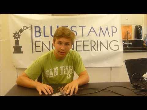
My first milestone was getting my magnetometer(compass) and motors to work in conjunction. I wrote code that took the data about north from the magnetometer and vibrated one of the pins based on the calculated heading. In theory, if the motors were oriented correctly the one facing north would always be the one vibrating. The motors vibrating north is just the first step in my project though, the more exciting part consists of the motors vibrating the direction of a user determined waypoint based on current gps location of the wearer. Unfortunately the gps doesnt work, so fixing it is where I’m headed next.
Starter Project
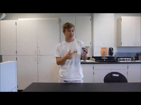
The mini-POV 4 is basically a strip of LEDs that light up in a configuration determined by firmware on the microcontroller. The POV (persistence of vision) leaves a trail of light when moved across quickly and can create a picture in light. I chose this starter project because I wanted to get some experience with interfacing a device with the computer. I had already soldered and programmed before, but I knew that my intensive project would require interfacing sensors and controllers with my computer. Indeed the interfacing gave me the most trouble, it worked the first time without any hitches on the built in firmware, but getting the drivers and the POV and the Processing IDE to understand each other was a challenge. The way that it works is that power comes from a AAA battery pack through a set of capacitors that smooth the current to the micro-controller in the center. A 12 MHz crystal keeps regular time for the micro-controller, which then blinks the LEDs based on that time. It also speeds up or slows down that blink time based on the potentiometer, a resistor that links rotation of the knob to its resistance. The controller then takes all of that information and tells the LEDs how to blink based on the firmware that I uploaded to it. (Hint: in the video it says BSE)
Hi Ethan,
Great projects. It seems that, counterintuitively, you are having fun with the problems that arise. Of course, the fun is in finding the solutions, not having the problems.
Congrats,
Saba
Woo hoo, so cool:)
Glad you had fun at your camp!
Aunt Janet