
Hello! My name is Eric, and I am a rising junior at Summit Shasta High. For my starter project, I decided to build the MintyBoost Charger, and for my main project, I decided to build the R/C robot tank controlled by a wireless PS2 controller. When I started Bluestamp, I had minimal engineering experience, maybe I could say making an LED light up with an Arduino in computer science class as experience, but really I was a complete amateur. I didn’t know what specific discipline of engineering that I would like to pursue; however, I knew that I loved building things (I build computers) and applying my knowledge in a tangible sense instead of only absorbing textbook material. After 6 weeks in this program, I can confidently say that engineering sparked my interest and will be a subject I would like to study and a career I would like to pursue. Computer engineering piqued my interest; however, I think many other disciplines of engineering are also in my realm of interest, as my future is not set in stone. I can also say that I became a better problem solver, as I powered through my obstacles and improved my self-learning skills. Overall, it was very fun building my project, very engaging listening to guest speakers, and enjoyable working with the instructors and learning at the same time.
FINAL PROJECT- R/C ROBOT NERF TANK

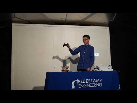
As I wrote above, I elected to build the R/C Robot Tank project. This project was appealing to me because I like robotics, and it looked fairly straightforward to build, while still being able to teach quite a lot, as well as providing lots of freedom for modifications. The final, completed project consists of the stock tank itself and the auto-loading Nerf flywheel dart launcher.

The tank itself is able to drive back and forward and pivot (like any tracked vehicle). It is controlled wirelessly from a PS2 controller and has a range of about 15 meters. The tank body is constructed from the Tamiya tank set/parts. The double gearbox is a Tamiya part as well. The wireless PS2 dongle and controller is an third party controller from Amazon. An Arduino Uno R3 (a programmable microcontroller) was used in conjunction with an Adafruit MotorShield v2. A motor shield is necessary because the Arduino itself does not have the capability to output enough current to drive motors, and because the Motor Shield has integrated PWM control, allowing simple, precise speed control of motors. PWM stands for pulse width modulation, and it controls the amount of electricity something receives. It controls electricity by alternating between on/off states very fast. For example, if we wanted to provide 50% power to a motor, the PWM controller would a switch between on half the time and off half the time, but does so very fast as to make it seem like a continuous flow. The stock documentation used AA batteries, however, I swapped that out for a 7.4v 2200 mAh lithium ion battery. Not only does it have a greater capacity and is rechargable, it also provides more current and voltage to the motors so that they will run faster. I had to replace the stock gearbox motors to ones rated for higher voltage as well, because the old ones were only rated for 3v and burned out with the new battery’s voltage. I also soldered on a spring push button switch from the battery to motor shield, for convenience sake.
On the sketch (microcontroller program/code) that I uploaded to the Arduino, I used the PS2x library, which allows the Arduino to process signals from the PS2 controller and set up events when buttons are triggered. When the buttons on the DPAD are pressed, the tank will move in that direction- forward, backward, or pivot right/left. The left trigger buttons rev up the flywheels (L1 is 50% speed, L2 is 100% speed) and R1 actuates the servo to push the dart into the flywheels and fire.

The Nerf dart flywheel dart launcher assembly consists of the wooden mounting block, a servo with pusher arm, a dart magazine (made of Depron Foam), and 2 Sparkfun hobby motors with Worker flywheels attached to each. It is mounted onto the tank by positioning another Tamiya Universal Plate on top of the tank body’s and attaching it with steel standoffs and nylon screws/spacers. The wooden plank assembly is then hot glued onto the upper plate and wires rerouted accordingly. The tank fires darts per the process documented in milestone three. From then on, the tank is fully wireless and complete. It can move at good speed backward and forward, pivot in places, and fire darts continuously because of the autoloader.
Documentation and Links:
Bill of Materials (BOM)
Arduino Project Source Code Pastebin
omniBotDestroyer> Source Code Download
Source Code:
#include
#include
#include
#include "utility/Adafruit_MS_PWMServoDriver.h"
#include

#define PS2_DAT        3
#define PS2_CMD        5
#define PS2_SEL        4
#define PS2_CLK        6
#define pressures   false
#define rumble      false

Adafruit_MotorShield AFMS = Adafruit_MotorShield();
Adafruit_DCMotor *flywheelOne = AFMS.getMotor(1);
Adafruit_DCMotor *flywheelTwo = AFMS.getMotor(2);
Adafruit_DCMotor *portSideMotor = AFMS.getMotor(3);
Adafruit_DCMotor *starboardSideMotor = AFMS.getMotor(4);
Servo autoloader;

PS2X ps2x;
int error = 0;
byte type = 0;
byte vibrate = 0;

void setup(){

  Serial.begin(57600);

  delay(300);  //added delay to give wireless ps2 module some time to startup, before configuring it
  pinMode(3, INPUT_PULLUP);
  autoloader.attach(9);
  Serial.println("tank motors");
  AFMS.begin();
  error = ps2x.config_gamepad(PS2_CLK, PS2_CMD, PS2_SEL, PS2_DAT, pressures, rumble);

  if(error == 0){
    Serial.print("Found Controller, configured successful ");
    Serial.print("pressures = ");
    if (pressures)
      Serial.println("true ");
    else
      Serial.println("false");
    Serial.print("rumble = ");
    if (rumble)
      Serial.println("true)");
    else
      Serial.println("false");
    Serial.println("Try out all the buttons, X will vibrate the controller, faster as you press harder;");
    Serial.println("holding L1 or R1 will print out the analog stick values.");
    Serial.println("Note: Go to www.billporter.info for updates and to report bugs.");
  }
  else if(error == 1)
    Serial.println("No controller found, check wiring, see readme.txt to enable debug. visit www.billporter.info for troubleshooting tips");

  else if(error == 2)
    Serial.println("Controller found but not accepting commands. see readme.txt to enable debug. Visit www.billporter.info for troubleshooting tips");

  else if(error == 3)
    Serial.println("Controller refusing to enter Pressures mode, may not support it. ");

//  Serial.print(ps2x.Analog(1), HEX);

  type = ps2x.readType();
  switch(type) {
    case 0:
      Serial.print("Unknown Controller type found ");
      break;
    case 1:
      Serial.print("DualShock Controller found ");
      break;
    case 2:
      Serial.print("GuitarHero Controller found ");
      break;
    case 3:
      Serial.print("Wireless Sony DualShock Controller found ");
      break;
   }
}

void loop() {

  if(error == 1) //skip loop if no controller found
    return;

  if(type == 2) //Guitar Hero Controller
    return;

  else { //DualShock Controller
    ps2x.read_gamepad(false, vibrate); //read controller and set large motor to spin at 'vibrate' speed

    if(ps2x.Button(PSB_START))         //will be TRUE as long as button is pressed
      Serial.println("Start is being held");
    if(ps2x.Button(PSB_SELECT))
      Serial.println("Select is being held");

    if(ps2x.ButtonPressed(PSB_PAD_UP)) {
      Serial.println("TRIGGERED");
      Serial.println(ps2x.Analog(PSAB_PAD_UP), DEC);
      portSideMotor->setSpeed(220);
      starboardSideMotor->setSpeed(200);
      portSideMotor->run(FORWARD);
      starboardSideMotor->run(FORWARD);
    }
    if(ps2x.ButtonReleased(PSB_PAD_UP)){
      portSideMotor->setSpeed(0);
      starboardSideMotor->setSpeed(0);
    }
    if(ps2x.ButtonPressed(PSB_PAD_RIGHT)) {
      Serial.println("TRIGGERED");
      Serial.println(ps2x.Analog(PSAB_PAD_UP), DEC);
      portSideMotor->setSpeed(105);
      starboardSideMotor->setSpeed(100);
      portSideMotor->run(FORWARD);
      starboardSideMotor->run(BACKWARD);
    }
    if(ps2x.ButtonReleased(PSB_PAD_RIGHT)){
      portSideMotor->setSpeed(0);
      starboardSideMotor->setSpeed(0);
    }
    if(ps2x.ButtonPressed(PSB_PAD_LEFT)) {
      Serial.println("TRIGGERED");
      Serial.println(ps2x.Analog(PSAB_PAD_UP), DEC);
      portSideMotor->setSpeed(105);
      starboardSideMotor->setSpeed
      (100);
      portSideMotor->run(BACKWARD);
      starboardSideMotor->run(FORWARD);
    }
    if(ps2x.ButtonReleased(PSB_PAD_LEFT)){
      portSideMotor->setSpeed(0);
      starboardSideMotor->setSpeed(0);
    }
    if(ps2x.ButtonPressed(PSB_PAD_DOWN)){
      Serial.println("I DON'T FEEL SAFE");
      Serial.println(ps2x.Analog(PSAB_PAD_DOWN), DEC);
      portSideMotor->setSpeed(220);
      starboardSideMotor->setSpeed(200);
      portSideMotor->run(BACKWARD);
      starboardSideMotor->run(BACKWARD);
    }
    if(ps2x.ButtonReleased(PSB_PAD_DOWN)){
      portSideMotor->setSpeed(0);
      starboardSideMotor->setSpeed(0);
    }
    vibrate = ps2x.Analog(PSAB_CROSS);  //this will set the large motor vibrate speed based on how hard you press the blue (X) button
    if (ps2x.NewButtonState()) {        //will be TRUE if any button changes state (on to off, or off to on)
      if(ps2x.Button(PSB_L3))
        Serial.println("L3 pressed");
      if(ps2x.Button(PSB_R3))
        Serial.println("R3 pressed");
      if(ps2x.Button(PSB_L2))
        Serial.println("L2 pressed");
      if(ps2x.Button(PSB_R2))
        Serial.println("R2 pressed");
      if(ps2x.Button(PSB_TRIANGLE))
        Serial.println("Triangle pressed");
    }
    if(ps2x.ButtonPressed(PSB_L1)){
      Serial.println("half speed rev");
      flywheelOne->setSpeed(120);
      flywheelTwo->setSpeed(120);
      flywheelOne->run(BACKWARD);
      flywheelTwo->run(BACKWARD);
    }
    if(ps2x.ButtonReleased(PSB_L1)){
      flywheelOne->setSpeed(0);
      flywheelTwo->setSpeed(0);
    }

    if(ps2x.ButtonPressed(PSB_TRIANGLE)){
      Serial.println("test lel");
      flywheelOne->setSpeed(20);
      flywheelTwo->setSpeed(20);
      flywheelOne->run(BACKWARD);
      flywheelTwo->run(BACKWARD);
    }
    if(ps2x.ButtonReleased(PSB_TRIANGLE)){
      flywheelOne->setSpeed(0);
      flywheelTwo->setSpeed(0);
    }

    if(ps2x.ButtonPressed(PSB_CROSS)){
      Serial.println("FULL SPEED REV");
      flywheelOne->setSpeed(255);
      flywheelTwo->setSpeed(255);
      flywheelOne->run(BACKWARD);
      flywheelTwo->run(BACKWARD);
    }
    if(ps2x.ButtonReleased(PSB_CROSS)){
      flywheelOne->setSpeed(0);
      flywheelTwo->setSpeed(0);
    }
    if(ps2x.ButtonPressed(PSB_L2)){
      Serial.println("FULL SPEED REV with cool spindown");
      flywheelOne->setSpeed(255);
      flywheelTwo->setSpeed(255);
      flywheelOne->run(BACKWARD);
      flywheelTwo->run(BACKWARD);
    }
    if(ps2x.ButtonReleased(PSB_L2)){
      flywheelOne->run(RELEASE);
      flywheelTwo->run(RELEASE);
    }
    if(ps2x.ButtonPressed(PSB_CIRCLE)){
      Serial.println("toggle maxspeed");
      flywheelOne->setSpeed(255);
      flywheelTwo->setSpeed(255);
      flywheelOne->run(BACKWARD);
      flywheelTwo->run(BACKWARD);
    }
    if(ps2x.ButtonPressed(PSB_R1)){
      autoloader.write(10);
      delay(250);
      autoloader.write(140);
      Serial.println("actuate servo");
    }

    if(ps2x.Button(PSB_L1) || ps2x.Button(PSB_R1)) { //print stick values if either is TRUE
      Serial.print("Stick Values:");
      Serial.print(ps2x.Analog(PSS_LY), DEC); //Left stick, Y axis. Other options: LX, RY, RX
      Serial.print(",");
      Serial.print(ps2x.Analog(PSS_LX), DEC);
      Serial.print(",");
      Serial.print(ps2x.Analog(PSS_RY), DEC);
      Serial.print(",");
      Serial.println(ps2x.Analog(PSS_RX), DEC);
    }
  }
  delay(50);
}
PRESENTATION NIGHT
MILESTONE 3
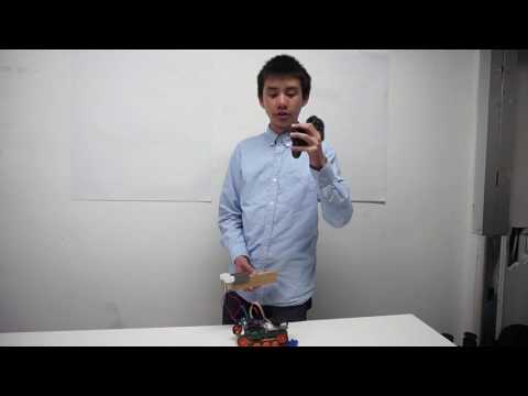
For my third milestone, I decided to dive into a modification. I purchased two flywheels and two hobby motors, and my goal was creating a flywheel Nerf dart launcher attached to my tank. The basic design was to have the darts fed by gravity, held by a magazine of sorts. The dart would then be pushed by a servo into the revved up flywheels. When the dart is accelerated and fired, another dart would come down from the magazine and the process can then be repeated. This was a straightforward system and, in theory, should work. I came into this modification planning that I would 3D print a lot of parts. I love 3D printing and I think that it is the future, and we had free access to one! Using Google Sketchup (a CAD program), I designed multiple parts that I planned to 3D print. However, when I came in on Monday, I was informed that the entire stock of filament for the 3D printer outside was used, and that more of it would not ship in until at least Wednesday. So, I had to utilize alternative materials and designs. Depron foam, hot glue, and wood was used. A 6″ long 0.75″ wide block of wood was cut and used as the main launcher assembly. It was by coincidence that the thickness of the wood was just perfect for the width between the flywheels to give an ideal grip for launching the dart. The flywheels attached to the motors easily (standard shaft diameters), and the motors were hot glued to opposite sides near the end of the wooden plank. Small Depron rectangles were cut and placed right before the flywheel motors to serve as guide rails, to ensure that the dart lays straight after being fed from the magazine. At this point, the flywheels can be revved up, and darts can be pushed into them to shoot! It works surprisingly well. This milestone’s video shows this.
My goal for this milestone was completing the Nerf dart launcher AND autoloader, however, the video was filmed before I could make the autoloader work consistently. It was nearly done, and essentially right after the video was shot, I had gotten it functioning reliably. The autoloader consists of a Depron-constucted magazine and a servo. The Derpon foam magazine is capable of holding 12 darts, plus one in the “chamber” (guide rails). A micro servo is hot glued near the end of the wooden plank, with a nylon cylinder hot glued onto the horn in addition. The nylon cylinder serves as an extension of the servo horn, so that when the servo is actuated, the extended “arm” will push the dart forward with sufficient distance. The basic principle of operation-
- Dart is loaded into guide rails
- Flywheels rev up to speed
- Servo arm is actuated
- Dart is pushed forward and propelled out of tank
- New dart falls from magazine onto now vacated guide rail (gravity powered)
- Another dart is now ready to shoot, process is repeated.
My project is nearing completion, my next step would be to find a way to mount it on the tank to make it completely mobile and to truly make it a Wireless R/C Robot Tank with Nerf Flywheel Dart Launcher.
MILESTONE 2

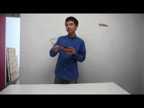
For my second milestone, I got the PS2 wireless controller working with the Arduino and ultimately was able to control the tank with it. The most important part of this is the Arduino PS2x library by Bill Porter, which allows the Arduino to read electrical signals from the PS2 controller wireless dongle. This allows us to get button states and joystick positions, which we can then use to trigger motors, servos, etc. Interfacing the PS2 controller with the Arduino is relatively straightforward. On the wireless PS2 controller dongle, I needed 6 wires to connect to the Arduino in order for the controller to properly work. Two of them are power (3.3v + ground), and the other four are DATA, CLOCK, SELECT, and COMMAND. The non-power wires can go to any digital pin, which can then be assigned to respective wires in the sketch. After that, I used some example PS2x code and added if statements for when the buttons are depressed and released. In my current version, I used the D-PAD for driving. When the up/down buttons are depressed, it will trigger both motors to run forward and backwards, respectively. When the left/right buttons are depressed, it will trigger the motors to run in opposite directions for pivoting. And of course, when any of the buttons are released, the motor speeds will be set to 0. The source code for this can be found
here.
At this point, I have completely finished the entire stock R/C tank project, and it is time for modifications. Some improvements I have made already include replacing the 5v portable USB charger with a 7.4v Li-Ion battery pack and replacing the gearbox motors with ones that are rated for higher voltage. The next modification I will be working on is the flywheel dart launching system. By the way, the omni-wheel servos no purpose other than elevating the Arduino and providing counterweight.
MILESTONE 1
For my first milestone, it was stated in my build plan that I would fully assemble my tank chassis, and gearbox and get the Arduino working and the MotorShield attached. After all of this, I would test the motors. The first thing I did was assemble the chassis and gearbox; that was fairly straightforward, as the Tamiya sets came with detailed and clear instructions. The gearbox gave me a little trouble, because the original one I got was partially built and incomplete (in terms of parts). Fortunately, there was a spare gearbox lying around and I was allowed to use that. The gearbox gear ratio is 38.2:1, meaning that for every 38.2 revolutions the motor shaft does, the drive shaft should rotate once. The chassis consisted of a Tamiya universal plate and track/wheel sets, which were both easy to assemble. For the MotorShield, the first step was getting it attached to the Arduino, which required me to obtain some stackable headers and solder them down and then put the MotorShield directly on top of the Arduino Uno. After that, I downloaded the Adafruit MotorShield V2.3 Arduino library and wrote a small sketch to run the motors. The sketch that I wrote is below:
#include <Wire.h>
#include <Adafruit_MotorShield.h>
#include "utility/Adafruit_MS_PWMServoDriver.h"

Adafruit_MotorShield AFMS = Adafruit_MotorShield();
Adafruit_DCMotor *portSideMotor = AFMS.getMotor(3);
Adafruit_DCMotor *starboardSideMotor = AFMS.getMotor(4);

void setup(){
  Serial.begin(9600);
  Serial.println("tank motors");
  AFMS.begin();
  portSideMotor->setSpeed(50);
  portSideMotor->run(FORWARD);
  starboardSideMotor->setSpeed(50);
  starboardSideMotor->run(FORWARD);
}

void loop(){
  delay(1000);
  portSideMotor->setSpeed(100);
  starboardSideMotor->setSpeed(100);
  delay(1000);
  portSideMotor->setSpeed(150);
  starboardSideMotor->setSpeed(150);
  delay(1000);
  portSideMotor->setSpeed(200);
  starboardSideMotor->setSpeed(200);
  delay(1000);
}
A short explanation: #include is used to include external libraries in a sketch, here MotorShield libraries are being included. The setup bracket is code that is executed once upon the Arduino’s startup. Here, I just set both motors to run on 50 speed (50/255) and run forward. The loop bracket is code that is run repeatedly indefinitely from startup after the setup code. Here, I change the speed of the motors every 1000 milliseconds. That is my first milestone, basically assembling the tank and testing motors.
STARTER PROJECT
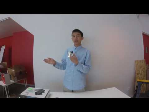
For my starter project, I decided to create the MintyBoost USB charger. The function of this device is simple. The Adafruit MintyBoost v3.0 uses 2 standard AA batteries and provides portable power for charging USB devices (phones, tablets, cameras, etc). The output it provides is 5V @ 500 mA, which is adequate for charging in most devices.

HOW IT WORKS
To be able to power a USB port for charging, the MintyBoost needs to convert the 3V power source (from 2 AA batteries in series) to 5V 0.5A power supplied through USB. It does this with a boost converter circuit. This is the heart of the MintyBoost kit. For this particular kit, the boost converter circuit consists of an inductor, an IC chip, a diode, and capacitors. There are 2 “sides” to the basic boost converter circuit. The left side has the inductor (which holds energy in a magnetic field), and is basically a closed circuit/short to the battery. The right side has the diode/capacitor and leads to the USB port/load. The IC chip acts as a switch/transistor and lies near the “middle” of the circuit. When the switch/transistor allows current to flow through, it creates a short to the battery and allows the inductor to build up energy in the magnetic field. When the switch is opened, the energy from the inductor has to travel through the diode/capacitor, building up its charge. The IC chip operates at 400 KHz, which means it “flips” the switch/transistor 400,000 times a second. The inductor resists change in current, but since the circuit is switching so fast, 400,000 times a second, it cannot possibly react that quickly and so the current flows through it to the capacitor. The other effect that switching so fast has on the circuit is that it prevents the inductor and capacitor from discharging fully; this is especially important for the capacitor (which resists change in voltage), since it has to stay topped off in order to maintain 5V continuous power. This 5V power is what allow us to charge our USB devices. The USB port has 4 wires in it. The two outermost wires are used for power, one for 5V and the other ground. This is where the 5V power from our boost converter is supplied. The 2 other pins are normally used for data, or can be used by the device to “tell” the computer that it want to draw power. In this case, it is used to allow Apple devices to accept power. For Apple devices to draw power, the data lines (D- and D+) have to maintain a certain voltage. This is where the 75k and 49.9k resistors come in, the take the 3V power from the battery and reduce it to 2V. When both data lines are 2V, the connected device will draw only 500 mA, which is the most the MintyBoost can provide.

Schematic for Adafruit MintyBoost v3.0
REFLECTIONS
Overall, I enjoyed this project. It was simple and practical, and quickly taught me basic principals of soldering. This kit was exclusively hardware based, involving no coding, and was simple to assemble. The only challenge I faced involved desoldering. In general, desoldering a mistake is painstaking and is something that I hope to only have to do sparingly. Also, it took me a long time to be able to understand how a boost converter worked. It simply did not make sense to me until lots of research and an explanation from a lovely instructor. My takeaways from this project are learning how to properly solder and desolder joints, understanding how a boost converter works, and, as a result, furthering my knowledge of electronics and circuits.