I am Dominic and I am a rising senior at Arrupe Jesuit High School. I am 17. I love to do research and gaming. My starter project is the Minty Boost. The Minty Boost charges phones with power from 2 AA batteries. My intensive project is an ergonomic keyboard. Here is one of the websites I referenced. This is a typing keyboard that I designed to reduce fatigue. At Bluestamp, I learned how to apply programming into common applications.
During this program, I was able to learn many things. First off, I learned that during the prototyping process, mistakes are OK. You have to make those mistake in order to know what you need to fix. The next thing I took away was that almost everything is fixable. I broke my PCB but I was able to find ways to fix it. My time at BlueStamp was fun and very educational for me.
Final Project: Ergonomic Keyboard

Documentation
Inspiration: http://jakemccrary.com/blog/2014/07/27/building-the-ergodox-keyboard/
Bill Of Materials: http://bit.ly/1gFju9X
Code: http://bit.ly/1gFoTxK
3D Models: ErgoDOX Case
Ergonomic Keyboard Third Milestone:
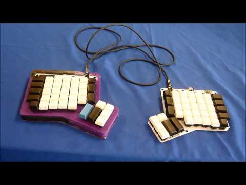
For my third milestone, I finished assembling my right hand case, I debugged my PCB and teensy, and I finished programming my teensy to be a keyboard. For the right hand case, I up scaled my model. This made the case a bit bigger to compensate for the area that the plastic shrinks. When debugging my PCB and teensy I first had to do continuity tests. For me to do this I had to map out which pins go to which column and row on the keyboard matrix. Once I got this mapped, I was able to test each row and column to make sure that the PCB was working. 2 columns did not receive a signal. These 2 columns were the ones with the broken traces. I then had to move on and repair these traces. At first I tried to repair the trace by making a new trace. This was hard to do. I then opted to connect the trace with wire to the pin on the PCB. Once I finished this, I did my continuity test again. This time everything worked.
For my program, I ran out of time to write a matrix program for my keyboard. I decided to use some stock keyboard code. This code works by scanning the rows and columns in a keyboard matrix. when a button is pressed, It reads what column and row was pressed. It then sends this information to the microprocessor which reads which key was pressed by what column and row it was. Here is a example of a Matrix.
Ergonomic Keyboard Second Milestone:
My second milestone is finishing my keyboard case and soldering on the switches to my keyboard. During this I ran into some problems. The first problem was with the 3D printed parts. I found out that during 3D printing, the plastic will shrink causing the part to be .5 or 1 mm smaller than it was suppose to be. I fixed this by lots of sanding and grinding. The second problem was clearance of the teensy. The teensy was too high on the cases and required me to desolder it. In the process of soldering it, I burnt out the teensy controller. I also tore off some of the traces on the PCB.
Ergonomic Keyboard First Milestone:
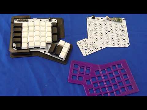
My first milestone was reached when I finished designing my case and soldering in the components on to my PCB. When designing the case, I learned how to use Inventor. It was really easy to learn so I was able to start designing fast. Here are 2 pieces that I designed.


I soldered the Teensy, I/O expander, 80 Diodes, and 2 TRRS connectors. The Teensy is the brain that allows the keyboard to work. The I/O expander works by providing the Teensy controller more inputs and outputs. The diodes are used in keyboard matrices to allow for multiple key presses to be registered. Lastly, The TRRS connector is used to connect the 2 halves together.
Starter Project: Minty Boost
The starter project I did was the Minty Boost. The Minty Boost allows you to charge your phone with 2 AA batteries. This works because it is a boost converter. Boost converters take a lower voltage and convert it into a higher voltage. Boost converters work by having a current flow through an inductor. The inductor is resistant to changes in current. When the switch is closed, the current flows through the inductor. When the switch is opened, the energy built up within the inductor is pushed through the diode. The diode moves the energy to the capacitor where it is stored. The capacitor slowly drips the energy to the load. The Minty Boost also has four resistors that works as a voltage divider. The Apple phone uses the voltage dividers to identify that the Minty Boost is safe to use.