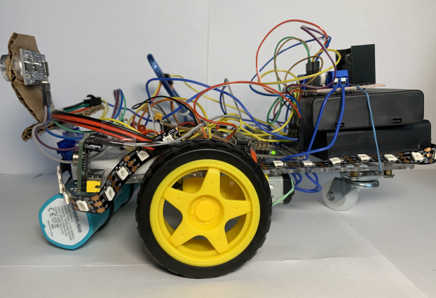
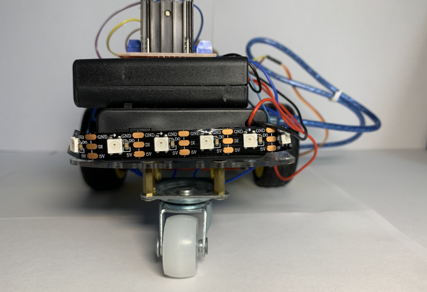
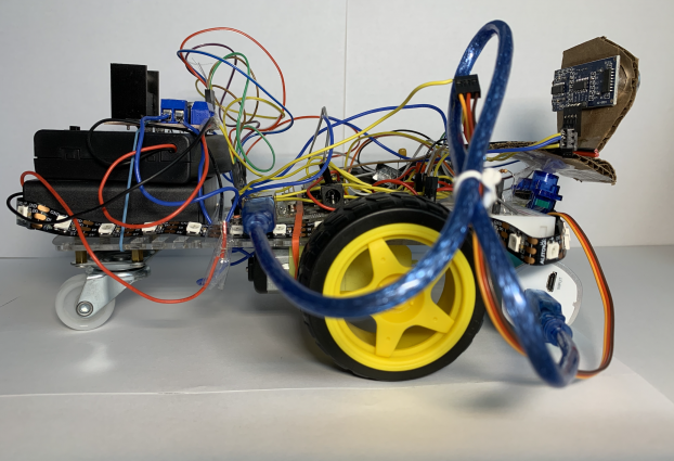
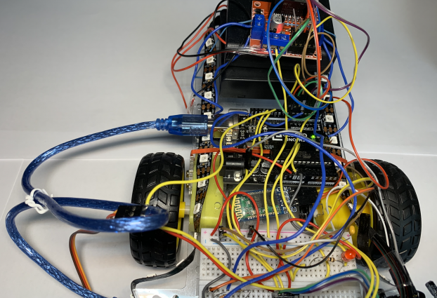
Project Overview
Functions
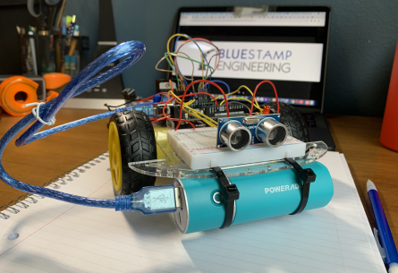
- Obstacle-Avoiding (Self-Drive) Mode
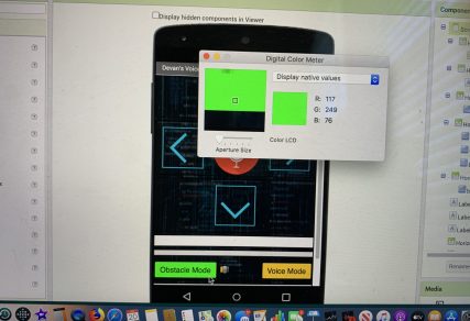
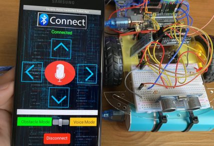
- Voice Command Mode (via Bluetooth)
- Remote Control Function
- Built-in Motion Detection
- Advanced AI Features
- LED Function
- Voice Features
Final Message
Virtual Demo Night
Final Milestone
PIR Motion Sensor
The PIR motion sensor is a sensor that detects motion through infrared waves. In other words, this sensor is able to detect heat which usually means that it senses a human. It takes very little to power it and doesn’t break easily. Its main purpose on this project is to detect if a person is in the way while in obstacle-avoiding mode. It was added to replace the built-in motion detection on the camera and ended up working really well.
Fifth Milestone
Adafruit LED NeoPixels
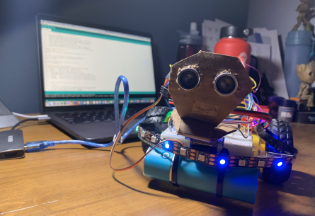
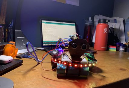
These Adafruit LED Neopixels are a simple instrument created to add and extra “wow” factor to the car. The tiny LEDs can be manipulated by code to be any color with described amounts of red, blue, and green. The frequency and colors are changed using for loops and map functions meaning that the colors as well as the speed in which they change can be altered. In this particular project, the NeoPixels increase in brightness as the car approaches 15 centimeters away from an obstacle and any closer triggers the lights to blink on and off red.
Double-Battery Circuit
With the need for more than 6 Volts of energy, the car was added an extra battery pack in order to compensate for the continuous addition of parts. This diagram essentially explains how this was carried out. The red black wire from the first battery pack remained in the Ground, the red from the first one and the black from the second one were connected, and lastly the red wire from the second battery pack was inserted to the 12 Volt slot on the motor L298N motor driver.
Fourth Milestone
SG90 Micro Servo 9g
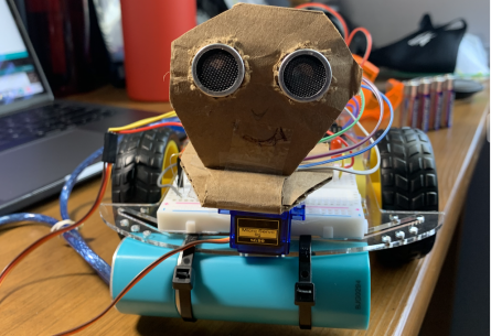
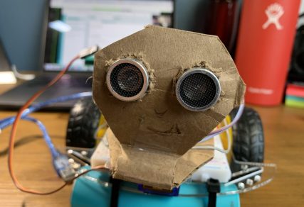
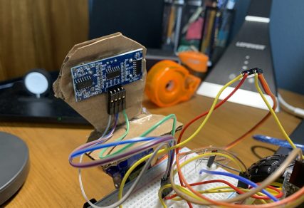
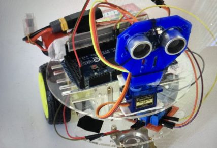
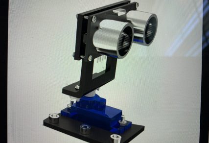
The SG90 Micro Servo 9g essentially acts as the neck for the robot. Its purpose is to move the HC-SR04 Ultrasonic Sensor left and right at a dictated degree. This servo sits at the front of the robot and connects to the Arduino using a breadboard and many jumper wires. The sensor was moved from the breadboard to holder and wires were also used to connect it back. It was then attached to the cardboard holder where it currently rotates it approximately 55 degrees when the car detects an obstacle within 30 centimeters away.
Servo Circuit
The SG90 Micro Servo 9g circuit is actually pretty simple. It is connected to the 5V and Ground ports on the Arduino via a breadboard, and is also connected to port 11 instead of port 4 as it was one of the few that remained open. The servo steals power from the Arduino which has the power source of a computer or a portable charger which means it is able to function without the battery switch on. Lastly, the servo was secured to the chassis with tape thereby completing the electrical component and enabling it to work on a flat surface.
Third Milestone
HC-06 Bluetooth Module
The HC-06 Bluetooth module connects the car to the Android. It essentially acts as the middleman between the electrical components of the car and the software components of the car. The module connects to the app created with MIT App Inventor to the Arduino on the chassis. It does this by receiving the integers sent by the app via Bluetooth and feeding it to the Arduino for it to process and carry out different functions.
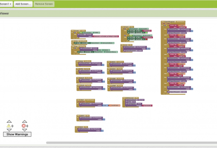
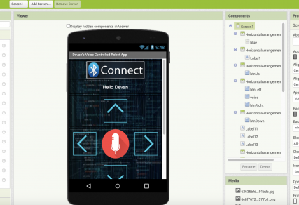
MIT APP Inventor
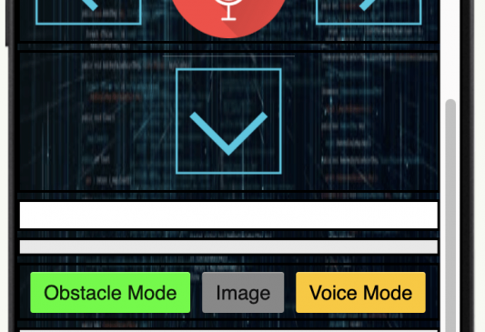
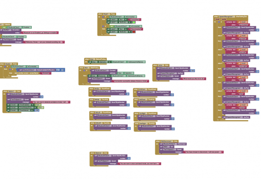
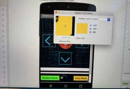
MIT App Inventor functions exactly like it sounds. In this project, its primary service was to be a platform for which I would create my app for the voice control command. This was carried out by using previous aia files found online and then inserting them into the site so that I could combine and edit. The website has two main parts, one is for the design and look of the app, and the other is the blocks of code of that app. Both enabled me to create a great app that was great in both design and software.
Second Milestone
HC-SR04 Ultrasonic Sensor
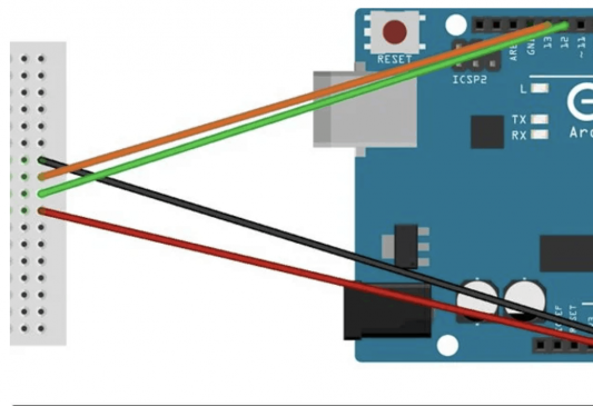
The HC-S04 Ultrasonic Sensor essentially acts as the eyes for the obstacle-avoiding robot. It does this by sending ultrasonic sound waves out and that bounce back, acting as an electronic form of echolocation. Once it gets this signal back, it sends the information to the computer to print. When an “if..else” statement is inserted in the code, the car carries out different functions depending on the distance. The sensor has four ports: Gnd, Echo, Trig, and Vcc, connected to the 5V port, digital port 12, digital port 13, and the ground port of the Arduino respectively. They each have a specific role in the code and allows the sensor to carry out its main function: if the sensor says that objects are within 30 centimeters, the far will back-up and turn, everything else, proceed.
Sensor-Motor Driver-LED Circuit
This circuit is the product of combining the LED, motor driver, and sensor circuits all to a singular Arduino. When building the ultrasonic sensor circuit, I tested it out on an LED before on actual motors. However, I ended up leaving it in because it served as a visual purpose of how and when the robot can detect objects in its path. The next thing to do was add the motor function by writing code that would enable that, but also create a smooth circuit without problems. The issue was that both the sensor and the motor driver needed the 5V port in the Arduino. So a breadboard was used to combine both of them in a row. This circuit is as simple as it is elegant. When the sensor detects that there are obstacles within 30 centimeters, the light goes on and the information is sent to the Arduino (and computer if connected), and then the program tells the motor driver to make the motors stop and allow the car to back-up and turn to where there are no obstacles.
First Milestone
Arduino UNO 3
The Arduino UNO 3 basically the brain of any Arduino-based robot. This board allows for open sourcing meaning various projects can be built off of it. It regulates inputs and outputs in analog and digital functions with the goal of connecting software to firmware. One can simply insert code on a computer and upload the software to the Arduino using a cable and when inserted into a circuit, the board can carry out many different functions.
L298N DC Motor Driver
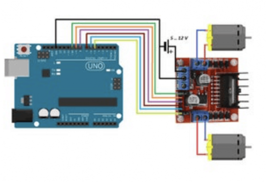
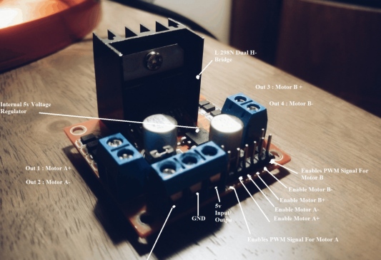
The L298N DC Motor Driver essentially does exactly what its name indicates. Its main purpose, specifically in this vehicle, is to control speed and rotation direction. The driver first takes the information sent by the Arduino as well as the energy from the battery pack, and regulates the motor(s) it is attached to by wire, thereby completing the circuit. There are two techniques on the driver, both for a different purpose. PWM is utilized for controlling speed by varying voltage input, and H-Bridge for controlling rotation direction by varying polarity of input voltage. This driver is an essential piece to the robot because it allows the Arduino to adapt to a project containing a running motor.
Arduino-Motor Driver Circuit
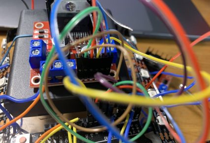
The complete circuit here enables the motors to run and the car to move forwards and backwards and different speeds. The main source of power comes from the four AA batteries in the battery pack. This is connected to the motor driver. A separate power source, either from the computer or a portable charger is connected to the Arduino so that it can be powered. Once the information (code) arrives to the Arduino, it is sent to the L298N DC motor driver. From there the motor driver distributes the information between each motor and using its two built-in systems, regulates the motors’ speed and rotation direction. Once this circuit is complete, the process repeats allowing the car to move continuously.


