
Magic Mirror
There are 3 components to the Magic Mirror: The mirror, the monitor, and the frame. The monitor is powered by a Raspberry Pi 3 that displays the Magic Mirror interface. The frame encases both the mirror and monitor to create the Magic Mirror illusion.
Engineer
Derin A
Area of Interest
Industrial Engineering/Electrical Engineering
School
Enka High School
Grade
Incoming Sophomore

My third and final milestone was based on my coding modfifications. I cloned a python repository from Github and made some changes in the config.js file. My modified code had a completely different layout than my normal code. It didn’t have any display errors and was pretty smooth.
Second Milestone
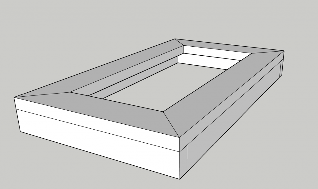
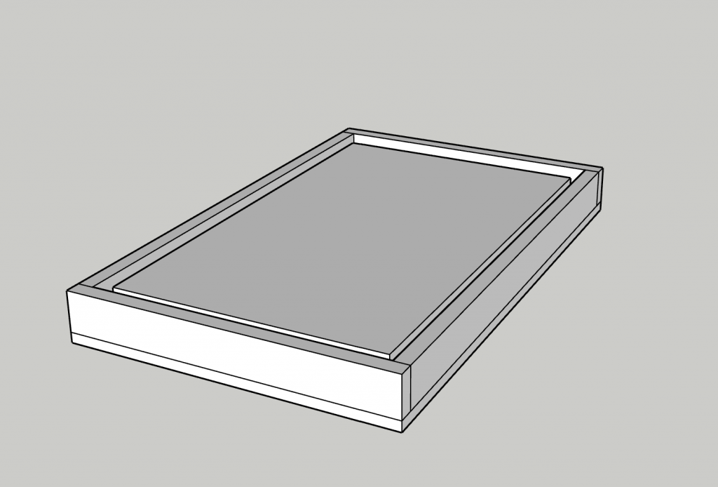
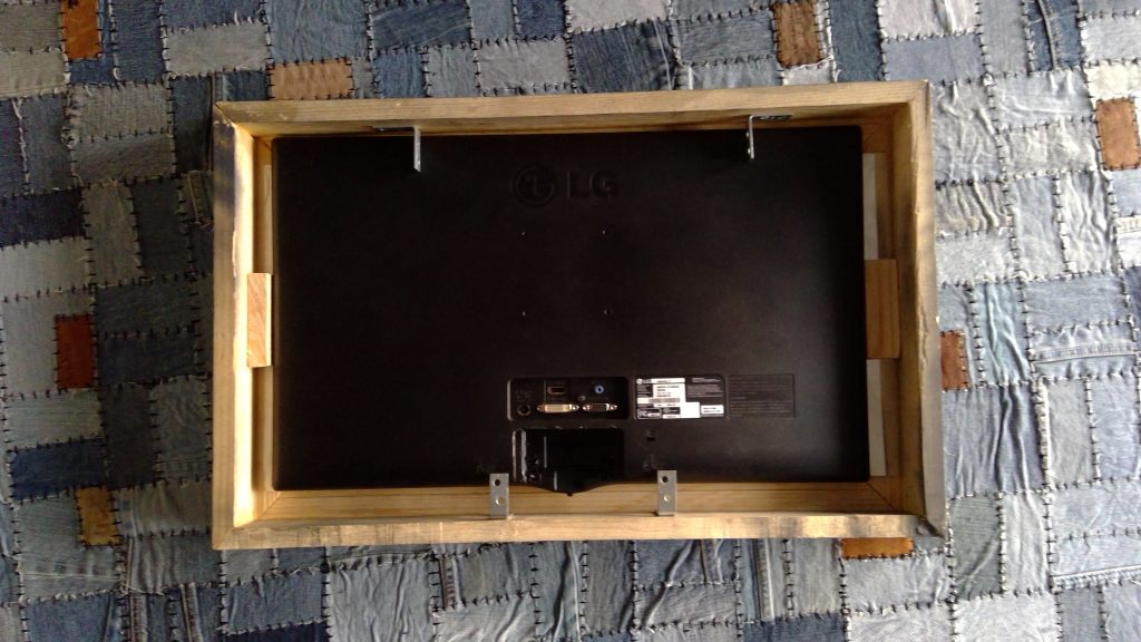
My second milestone was based on the frame of my mirror. I made a 3D model using SketchUp and created a 3D model of my frame. Later on, when I was building my frame I used my SketchUp model as a reference. For my frame, I cut 8 pieces of wood with 45-degree angles each. I assembled two frames using 4 pieces of wood per frame and wood glued the 45-degree cuts together. Then, I mounted the “side frame” onto the “front frame” using wood glue again. As I was waiting for the glue to dry, I cut my plexiglass to shorten its length. During the cutting process, I made sure to place tape across the edge I was cutting so that the cracks didn’t propagate. Even when I was finished with the mirror, I left the tape on to avoid any major damage. I put “wood putty” in small gaps all along the frame and waited for it to dry. Then I put my plexi glass inside my frame and sandwiched it there with my monitor. I drilled holes in the interior of my frame to apply corner brackets and nailed them in place to make sure they were strong enough to hold the monitor and the plexiglass in place. Shortly after that, I took off my monitor and mirror to avoid painting them, and I applied dark-gray spray paint to the frame. Finally, I put everything together.
First Milestone
My First Milestone for the Magic Mirror Project was to complete my code. I was able to display the time, the current news. I was also hoping on displaying the weather but for some reason that didn’t work. I plan on fixing the weather problem by next week.
Starter Project
My starter project was the Exploding Star Color Organ. The light organ lights up a group LEDs based on the sounds in the environment. This project consists of 25 LEDs with the colors red, green and yellow, 4 capacitors, an 8 pin IC with an 8 pin socket, a 16 pin IC with a 16 pin IC, 12 red LEDs, 7 yellow LEDs, 6 green LEDs, a battery snap, 2 potentiometers, 7 transistors, 11 resistors, and 9 volt battery.
Demonstration
How it works
The microphone picks up sounds in the environment which then triggers certain groups of different colored LEDs to light up. If there is a constant sound source, the LEDs which are alligned as a star will continuously light in groups, each group being a circle of LEDs. Each group of LEDs has a different color than the ones next to it. The sounds picked up by the microphone get processed by the ICs which then send signals to the LEDs in order to light them up. The transistors act as amplifiers, so that the LEDs have enough power to light up. The resistors avoid the circuit from overheating. The potentiometers can be adjusted to set the sensivity of the microphone so that it can trigger LEDs with less sound. To power all the components the system uses a 9 volt battery.
Mini POV Schematic

Schematics
