My name is David. I’m a rising junior at Denver Jewish Day School, and my passions are music and engineering. For my projects, I decided to bring those two together and build musical equipment. For my “starter” project, I built an analog delay from a kit and added reverb functionality to it as well from a different kit. Once those two were integrated together, I built a small wattage tube amplifier for my main project to gain a better understanding of the equipment that I use every day for my musical endeavors. Building these projects has given me a basic overview of how musical technology works and I intend to apply it in the future, combining the two things I love: music and engineering.
Analog Delay Pedal:
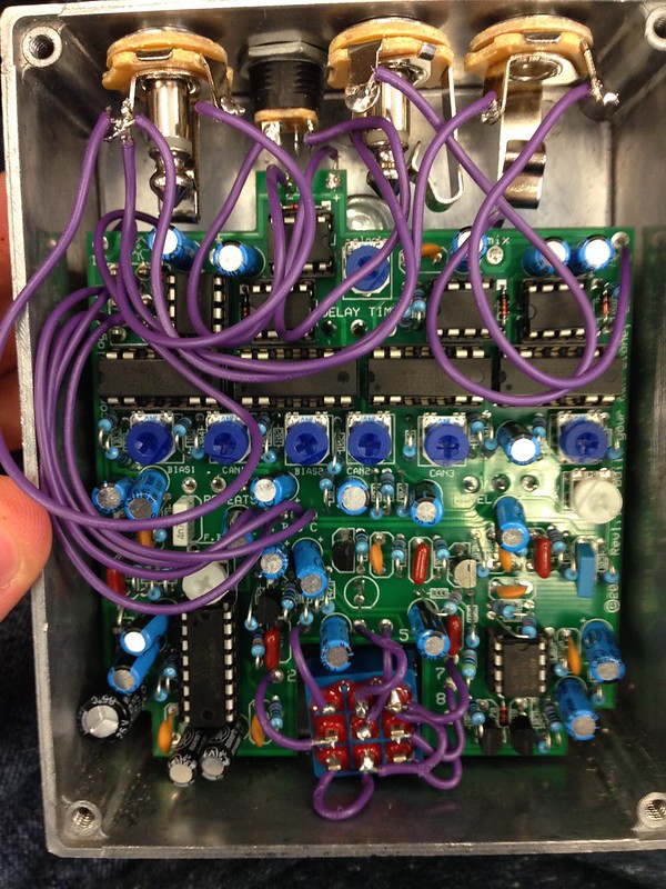
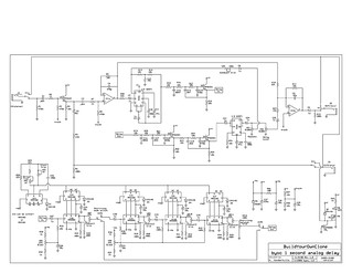
Here is the schematic of the delay courtesy of BYOC electronics:
Here you can see a fully documented video of the delay portion of the pedal, including a description of the parts inside, clock circuits, delay circuits, oscilloscope readings, and delay level attenuation:
Here are 3D models and mechanical drawings for the final casing:
The Timing Circuit:
The delay pedal is driven by 5 V3102D IC’s. These are all dual phase clock generators and this is the first topic addressed by oscilloscope readings in the video. Their period is controlled by a 1 MegOhm potentiometer. The more clockwise it is turned, the longer the period is, therefore producing longer delay times. The range of delay times available is controlled by an internal trim pot. As delay time increases, fidelity of the signal decreases. This is due to the nature of the analog delay IC’s.
The Delay Circuit:
The actual delaying of the signal comes from 4 v3205D chips. These are collectively driven by the clock IC’s aforementioned. Each chip has 4096 steps in it and transfer from one to the next is caused by clock pulses. The delay mode is controlled by a DPDT switch. When in short mode, 3 of the V3205D’s are bypassed. In long mode, they are added back into the circuit, allowing for approximately 4 times the amount of delay but at the cost of signal clarity.
The Op-Amp:
The signal from the guitar is made loud enough to work with by the op-amp IC, the TL072CN. This effectively boosts the amplitude while retaining the original signal clarity.
Feedback Control:
If there were no feedback control, there would only be one delay after the original signal. Repeated delays are achieved through sending part of the output signal back through the delay circuit. This allows for repeated delays from just one input signal. However, as the signal is passed through each 4096-step IC each time, it loses more and more clarity. This is why, as repeats increase, the signal becomes closer to sheer noise. When repeats/feedback is turned all the way up, the signal is infinitely sent back through the chips, effectively creating noise. However, there is still a sinusoidal aspect to it, as when delay time is turned down and period gets shorter, the pitch of the sound gets higher. Combination of these two controls can yield dubstep-type sounds, as shown in the video above.
Level Control:
Volume of the delay signal in comparison to the original dry signal is controlled by the level potentiometer. This controls how much of the delayed signal section is allowed to pass through to the mixed output. The remainder is sent to ground. Through this, amplitude of the delay signal can be controlled. As amplitude decreases, so does the audible presence of the delay in the mixed output.
Reverb Addition:
To add an extra level of functionality to the delay, I added another pedal’s reverb unit to it in series. Connection was as simple as wiring the output jack of the delay to the input jack of the reverb and finally forgoing all jacks in between, instead substituting them for wires.
Here you can see the schematic from PedalParts.co.uk:
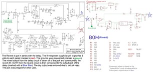
The PCB that is actually constructed through the kit is merely a conditioner for the Belton Brick, which generates all the reverb. It was known that it would have to be a digital reverb, as analog reverb requires real springs, plates, or even a large room. This made it only possible to analyze the reverb unit as a whole, rather than finding and probing each “block” for functionality. Here you can see the video showing the full demo in conjunction with the delay:
Delay/Reverb Unit Milestone:
Tube Amplifier:
For my main project, I built a tube guitar amplifier. Tubes generally create a warmer feel than transistors which exist in their solid-state opposites, transistors. This is due to an increased dynamic range. This makes tubes extremely necessary to generate the classic tones that guitar amplifiers have had for years.
Here you can find the schematic, courtesy of Slacker at diystompboxes.com.
Here you can see the fully documented video, explaining the various parts that a tube amplifier entails. The schematic is talked through in depth and oscilloscope readings are shown to help explain various stages of amplification. Tube functionality is also explained as an integral part to the amplification system:
Here are 3D models and mechanical drawings for the final casing:
The Tubes:
This amplifier is driven by vacuum tubes, which function by harnessing the power of electron behavior in a vacuum. The cathode is heated by a filament at 6.3 volts (a relatively standard voltage across many tubes) to help promote the ionization of electrons to flow to the anode. This flow is relatively backwards as it flows from the negative cathode to the positive anode. However, there is a third electrode involved to control the flow, called the gate. Its voltage is generally kept relatively negative in comparison to the cathode, disallowing electrons to fly through space. These three electrodes constitute the name: triode. As voltage is applied to the gate to make the charge more positive, electrons are allowed to flow from the cathode, past the gate, and to the anode creating a high voltage at the plate that mimics the voltage at the gate. With this concept applied, if a sound, or oscillation of voltage is applied to the gate, amplified sound will be created at the plate. This functionality is very similar to a transistor and as such, was the predecessor to them. The two both work by controlling voltage flow from one electrode to the other via a gate in the middle. However, tubes usually exhibit a greater level of dynamic, allowing for the warmer sound guitarists tend to prefer. The tubes in this particular amplifier are 12AT7s from Electro Harmonix. They are both dual triode tubes, meaning that each has a triode tube inside of it and their own heaters, with one shared, totalling nine pins.
Voltage Regulation and Operation:
This amplifier is provided 21.3 volts by a DC power supply. The voltage for the heaters is regulated by an LM317 to be 12.6 volts (6.3 for each heater in the tube) and as a result, an immense amount of heat is created. This causes need for a relatively powerful heatsink. In the video, a makeshift heatsink is made from the side of a pedal casing and dissipates enough heat for the LM317 to function, however a much better one will be needed for the final construction. The voltage is also connected to the output transformer at an unregulated amount. It flows through the transformer and into the power tube after that, ultimately controlling the final output to the speaker. If voltage were stepped up (ignoring the LM317’s immense heat dissipation), more power tubes would be needed to help regulate flow through the transformer. This is how amps with more power tubes operate at higher voltages to achieve a higher volume.
The Controls:
The amplifier is controlled by two 1 megohm potentiometers. The volume knob also functions as gain control, as when volume is increased, audible breakup occurs. This breakup creates the warm crunch that many guitarists seek from an amp overperforming, past what it is capable of providing cleanly. The tone control grounds higher frequencies through filter capacitors, creating a warmer tone that is less piercing.
Output Stage:
The output transformer steps up the voltage to operate the speaker. Its output impedance is supposed to match the speaker, however there was a discrepancy in the actual impedance of the transformer. Some sources stated 4 ohms, others stated 8. However, in its current operational stage with a 4 ohm speaker, it appears to work fine. The only potential sign of malfunction is a fuzziness or lack of clarity in the sound from the speaker. This could also be due to lack of speaker build quality.
Oscilloscope Operation:
The purpose of an amplifier is to simply take the original signal, match its period, and boost the amplitude of the sine waves to mimic the original sound but louder. Tubes tend to offer a bit more dynamic of volume, and therefore can create warmer gain and crunch structures. Upon examination, a weird spike was found after the down-slope of every wave. It could be a filter, however the true reason for its presence is unknown.
Electrical Explanation:
First, the LM317 takes the 21.3 volts and converts it to 12.6 for the heater filaments of the tubes. The unregulated voltage goes through the output transformer and is regulated by the power tubes. The guitar input signals hits the first pre-amp tube before it flows to the EQ and volume sections. Here, the volume control functions by grounding all frequencies, while the tone control only grounds the higher frequencies by filter capacitors. After this, the signal hits the other pre-amp tube before it hits the output tubes’ gates which are run in parallel.