
My main project is a MIDI-Based Audio Controller. When connected to a computer running music software, the controller can play fully customizable notes or tracks at the press of a button. My experience at BlueStamp was an introduction not only to soldering and electrical circuitry, but the engineering mindset — the perseverance to solve problems and get a job done.
Intensive Project: Audio MIDI Controller

For my main project, I selected the Audio MIDI Controller. MIDI stands for Musical Instrument Digital Interface, and it’s a means of communication between devices like this controller and a computer. When this controller is hooked up with music software on my laptop, it serves as a soundboard that can play fully customizable notes or tracks when buttons are pressed.
I chose this project because it was the best of both worlds — not only between music and computers, but between the hardware and software aspects of engineering. I wanted to cover all the bases with a cool, interactive project.

Materials and Tools
The cost of the parts amounted to about $80 including the Arduino, $35 without.
| Item | Vendor/Link | Part Number | Qty | Cost |
| Arduino Mega 2560 (a Due will work fine too) | Sparkfun | DEV-11061 | 1 | $45.00 |
| Sanwa OBSF-24 Arcade Button White 10pcs | Ebay | OBSF-24 | 1 | $10.00 |
| Plastic Enclosure Box GREY 9.84 X 7.09 X 1.97″ | Digikey | RM2095S | 1 | $12.00 |
| Rotary Potentiometer – 10K OHM, LINEAR | Amazon | B00DN7MSXY | 1 | $6.00 |
| Pot Slide Potentiometer 10K OHM .25W 60MM | Digikey | PTB6043-2010BPB103 | 2 | $9.00 |
| Total Cost: | $82.00 |
I didn’t need any particularly complicated tools for this project. I used:
- A power drill to fit the buttons and knobs.
- Various diamond files of different shapes and sizes for precision mounting.
- A power jigsaw to cut holes for the sliding potentiometers.
- A hand saw to cut holes to mount the Arduino on the bottom of the board.
- A soldering iron and solder.
- Jumpers to insert into the digital pins.
- Heat shrink to insulate my wiring.
Milestone #2 Video: Soldering and Configuring
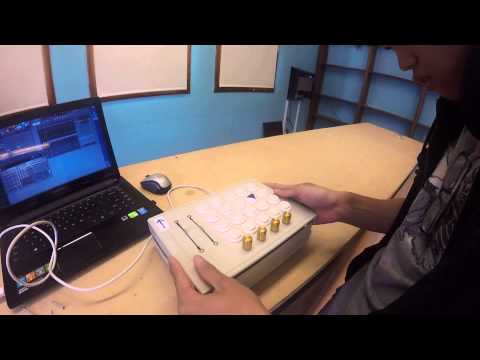
By this milestone, I had mounted the Arduino (and the final 10 buttons.) However, the buttons wouldn’t do anything unless I connected them to the Arduino. Using the Instructable’s provided schematics as loose guides, I soldered each button to a ground wire and a separate pin wire. Each button corresponds to a pin in the Arduino Mega, incrementing upwards from 2 to 21.
When I finished soldering, the wiring looked as you can see below:

Programming and Software
The wires were now hooked up to my Arduino Mega (except the sliders, which are secondary.) Now, I had to program the Mega so it could play sounds when buttons were pressed. The documentary I followed had code ready for use, but I knew it would be old, possibly outdated, and definitely non-supportive of a 20-button configuration. I tweaked that Arduino code to work with my board. You can find it uploaded here.
With the code, the Arduino registers when a button is pressed and sends a serial message to the PC with info like the note’s pitch, channel, and velocity.
I installed the program, Serial – MIDI Converter, to convert my serial messages into readable MIDI signals. I then used MIDI-Yoke to open a port that I could use to send MIDI to my music program, Fruity Loops Studio 12. Finally, I configured FL Studio to accept the MIDI-Yoke port. My music synthesizing board was complete.
Milestone #1 Video: Mounting and Filing
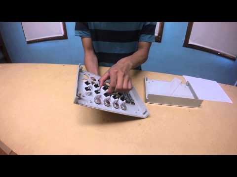
This milestone took the most idle work to achieve; I drew a schematic design for the controller’s lid, printed it out, and started drilling. The most I learned was using the power drill to drill the holes for the 20 arcade buttons and the other smaller holes. After that, I was trained in the jigsaw, a power tool that could cut material in a straight line. This I had to use for the sliders.
I had a lot of filing to do for this milestone. Initially, none of the arcade buttons fit in the holes I drilled. The slider holes were blocked by small bubbles of melted plastic (a parting gift from the jigsaw I used.) The knob potentiometers didn’t quite fit, either. So I filed for a very long time, probably 4-6 hours of labor total, with diamond files of 3 different sizes and probably 6 different shapes. Once the buttons could fit in the holes I originally drilled for them, I then filed in two notches for the buttons’ tabs to lock into place.
Getting Started / Design
This project was inspired by a documented project of the same name, a DIY Instructable I found online through BlueStamp Engineering. (You can find it here!)
My materials, design, and code were inspired by this Instructable. At the same time, I deviated from his design and directions heavily, so my project was more challenging and independent.

Left: the documented controller. Right: my completed controller.
When I first decided to do this controller and picked parts out, I set some parameters:
- The board would feature 20 arcade buttons in a 4 x 5 array.
- The board would have 4 knob potentiometers and 2 slider potentiometers that can be dynamically configured.
- To fit all of these parts comfortably, I envisioned a board of about 10 inches by 7 inches.
- Because I’m left handed, I’d put the sliders on the right side.
- I’d have to use an Arduino Due or Mega (since the other Arduinos don’t have enough pins.)
With this in mind, I drew a 2D CAD to form a design for my board.
Since I could no longer use the schematic or design in the Instructable, I created my own. This was the first step after getting my parts — setting up how the board would look and where the buttons, sliders, and knobs would fit.
My final design for the board’s surface is shown below. (It can also be seen in the Milestone #1 Video.)

Starter Project: Simon Says
My starter project was the SparkFun Simon Says Kit! The link is clickable. It came with a pre-programmed IC that runs the board.
This board is a fun game where the button LEDs light up in a specific pattern, and you try to press the buttons in the same order. As the game goes on, the pattern becomes more and more complicated.
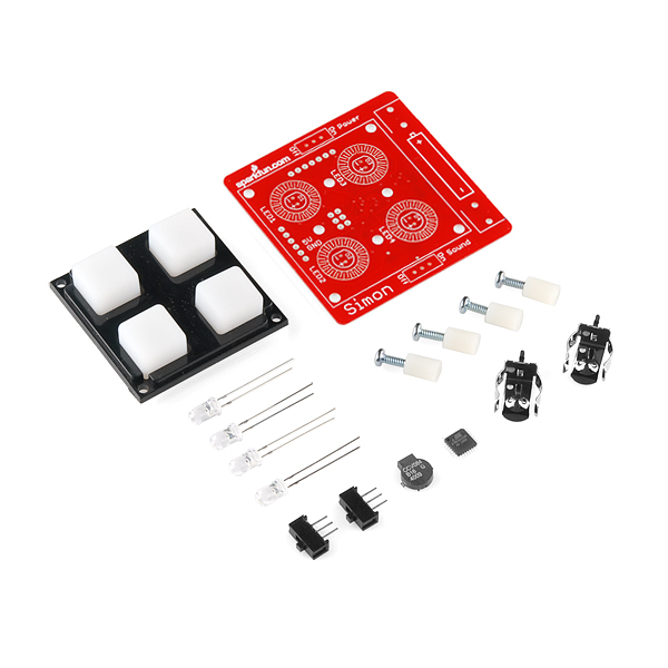
The battery clips — one for positive, one for negative — connect to the power and sound switches as they run directly through another, smaller IC, at which point a capacitor and an inductor also enter the circuit to regulate power and store energy. The sound switch’s circuit also includes the buzzer to emit sound when needed. The circuit then branches into the 4 LEDs, with one 330Ω resistor per LED to control the current. The 32-pin IC is located smack in the middle of the board and essentially connects to everything else.
Process
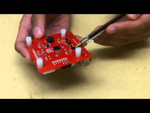
My instructors warned me of the project’s difficulty. This was my first time soldiering on a surface mount, and the pieces were incredibly tiny and difficult to place on the board (some parts were less than a millimeter wide.) When it came to such small parts, tweezers became my most valuable tool. After soldering in the battery clip, I realized I had soldered it in backwards. De-soldering the clip from the board took 70 minutes, 2 instructors, and a lot of patience — all because of one tiny mistake. I’d say one of the biggest lessons I’ve learned is that intense attention to detail is crucial when working on hardware — it’s hard to undo your mistakes.
Schematic
