
RC Tank
The RC Tank is a robotic, remote controlled tank that is powered by a gearbox and an arduino.
Engineer
Darryl F
What I want to do in the future
Mechanical Engineering
School
The Park School of Baltimore
Grade
Incoming Sophomore
Reflection
When I first started this program, I did not have too much knowledge about different electrical devices and how to wire things. I also did not know how to solder. By the end of the project, I learned how to solder and how to wire things electrically. I had a lot of fun making this project. I learned a lot from the mistakes I made. I also got better at speaking throughout my videos. It was a great experience and I hope to come back next year.
Final Milestone
My final milestone was to get the motors working and then have the tank be controlled by a PS2 controller. My steps for this milestone was first I wired in the motors and motor driver. Then I had some code for my specific functions: to go forward, to go backward, and to move left and right. My next step was to wire my PS2 controller to my Arduino. The last thing that I had to do was combine the PS2 code with the code for the functions.
I used an L298N for this project. It has two enable pins which are used to enable and disable the device. It also has emitters, carriers of current, on each bridge, which are connected together.. The L298N also has an H-bridge. The H-bridge controls the DC motor. It has four switches in each of its corners. See an example diagram of an H-bridge in figure 5. When you tell the motor the move clockwise, the top left, and bottom right, ground, switch close. When you tell the motor to move counter clockwise, the top right, and bottom left, ground switch close and the other two open. This is how the motor spin in either direction. For example in figure 5, when Q1 and Q3 are closed and Q2 and Q4 are open, the motor spins clockwise. When Q2 and Q4 are closed and Q1 and Q3 are open, the motor moves counter-clockwise.
The way that I wired my PS2 controller is that there are nine different ports, (see in figure 4). I was supposed to only use six of them. The ports are labeled, data, command, vibration, ground, 3.3V, attention, clock, and two unknowns. I didn’t use the two unknowns and the vibration. I connected them to my Arduino. Only two of then needed PWM pins, attention and command.
One mistake that I made in this milestone is that I used a bad wire to wire my motor to ground. This was one of the reasons why my project wasn’t working at first. Another mistake that I made was that I had wired my PS2 controller to the wrong pins. I had to figure out which ones needed PWM pins and had to rewire it and code it again. One other mistake was that I had made the tank treads too tight and it didn’t allow the tank wheels to spin so I had to redo them. The last mistake that I made was that I had accidentally wired the right motor the wrong enable which made it so that the right side of the gearbox wouldn’t turn.One thing I learned during this milestone was how to wire motors to an Arduino and how to code motors. Before this I had never had experience with wiring motors but now I have it down. Another thing that I learned was how to wire a PS2 controller to and Arduino and how to code it. I thought that it would be complicated but it was fairly simple. Overall, I really enjoyed this project. I made a lot of mistakes that I eventually learned from. This was a great hands-on project and I am satisfied with the outcome.
Link to how I wired the motors:
Buy an L298N:
#include <L298N.h>
#include <PS2X_lib.h> //for v1.6

//pin definition
#define EN 10
#define IN1 9
#define IN2 8

#define ENB 11
#define IN3 13
#define IN4 12


//create a motor instance
L298N motor(EN, IN1, IN2);
L298N motor2(ENB, IN3, IN4);

PS2X ps2x; // create PS2 Controller Class

//right now, the library does NOT support hot pluggable controllers, meaning
//you must always either restart your Arduino after you conect the controller,
//or call config_gamepad(pins) again after connecting the controller.
int error = 0;
byte type = 0;
byte vibrate = 0;

void setup() {

Serial.begin(9600);
motor.setSpeed(150); // an integer between 0 and 255
motor2.setSpeed(150);
//CHANGES for v1.6 HERE!!! **************PAY ATTENTION*************

error = ps2x.config_gamepad(3,6,5,2,true, true); //setup pins and settings: GamePad(clock, command, attention, data, Pressures?, Rumble?) check for error

if(error == 0){
Serial.println("Found Controller, configured successful");
Serial.println("Try out all the buttons, X will vibrate the controller, faster as you press harder;");
Serial.println("holding L1 or R1 will print out the analog stick values.");
Serial.println("Go to www.billporter.info for updates and to report bugs.");
}

else if(error == 1)
Serial.println("No controller found, check wiring, see readme.txt to enable debug. visit www.billporter.info for troubleshooting tips");

else if(error == 2)
Serial.println("Controller found but not accepting commands. see readme.txt to enable debug. Visit www.billporter.info for troubleshooting tips");

else if(error == 3)
Serial.println("Controller refusing to enter Pressures mode, may not support it. ");

//Serial.print(ps2x.Analog(1), HEX);

type = ps2x.readType();
switch(type) {
case 0:
Serial.println("Unknown Controller type");
break;
case 1:
Serial.println("DualShock Controller Found");
break;
case 2:
Serial.println("GuitarHero Controller Found");
break;

}
}
void loop() {
/* You must Read Gamepad to get new values
Read GamePad and set vibration values
ps2x.read_gamepad(small motor on/off, larger motor strenght from 0-255)
if you don't enable the rumble, use ps2x.read_gamepad(); with no values

you should call this at least once a second
*/


if(error == 1) //skip loop if no controller found
return;

if(type == 2){ //Guitar Hero Controller

ps2x.read_gamepad(); //read controller

if(ps2x.ButtonPressed(GREEN_FRET))
Serial.println("Green Fret Pressed");
if(ps2x.ButtonPressed(RED_FRET))
Serial.println("Red Fret Pressed");
if(ps2x.ButtonPressed(YELLOW_FRET))
Serial.println("Yellow Fret Pressed");
if(ps2x.ButtonPressed(BLUE_FRET))
Serial.println("Blue Fret Pressed");
if(ps2x.ButtonPressed(ORANGE_FRET))
Serial.println("Orange Fret Pressed");


if(ps2x.ButtonPressed(STAR_POWER))
Serial.println("Star Power Command");

if(ps2x.Button(UP_STRUM)) //will be TRUE as long as button is pressed
Serial.println("Up Strum");
if(ps2x.Button(DOWN_STRUM))
Serial.println("DOWN Strum");


if(ps2x.Button(PSB_START)) //will be TRUE as long as button is pressed
Serial.println("Start is being held");
if(ps2x.Button(PSB_SELECT))
Serial.println("Select is being held");


if(ps2x.Button(ORANGE_FRET)) // print stick value IF TRUE
{
Serial.print("Wammy Bar Position:");
Serial.println(ps2x.Analog(WHAMMY_BAR), DEC);
}
}

else { //DualShock Controller

ps2x.read_gamepad(false, vibrate); //read controller and set large motor to spin at 'vibrate' speed

if(ps2x.Button(PSB_START)) //will be TRUE as long as button is pressed
Serial.println("Start is being held");
if(ps2x.Button(PSB_SELECT))
Serial.println("Select is being held");


if(ps2x.Button(PSB_PAD_UP)) { //will be TRUE as long as button is pressed
Serial.print("Up held this hard: ");
Serial.println(ps2x.Analog(PSAB_PAD_UP), DEC);
}
if(ps2x.Button(PSB_PAD_RIGHT)){
Serial.print("Right held this hard: ");
Serial.println(ps2x.Analog(PSAB_PAD_RIGHT), DEC);
}
if(ps2x.Button(PSB_PAD_LEFT)){
Serial.print("LEFT held this hard: ");
Serial.println(ps2x.Analog(PSAB_PAD_LEFT), DEC);
}
if(ps2x.Button(PSB_PAD_DOWN)){
Serial.print("DOWN held this hard: ");
Serial.println(ps2x.Analog(PSAB_PAD_DOWN), DEC);
}


vibrate = ps2x.Analog(PSAB_BLUE); //this will set the large motor vibrate speed based on
//how hard you press the blue (X) button

if (ps2x.NewButtonState()) //will be TRUE if any button changes state (on to off, or off to on)
{


if(ps2x.Button(PSB_L3))
Serial.println("L3 pressed");
if(ps2x.Button(PSB_R3))
Serial.println("R3 pressed");
if(ps2x.Button(PSB_L2))
Serial.println("L2 pressed");
if(ps2x.Button(PSB_R2))
Serial.println("R2 pressed");
if(ps2x.Button(PSB_GREEN))
Serial.println("Triangle pressed");

}


if(ps2x.ButtonPressed(PSB_RED)){ //will be TRUE if button was JUST pressed
Serial.println("Circle just pressed");
motor.forward();
motor2.forward();


}
if(ps2x.ButtonReleased(PSB_RED)){ //will be TRUE if button was JUST pressed
Serial.println("Circle just released");
motor.stop();
motor2.stop();


}


if(ps2x.ButtonPressed(PSB_BLUE)){ //will be TRUE if button was JUST pressed
Serial.println("Circle just pressed");
motor.backward();
motor2.backward();


}

if(ps2x.ButtonReleased(PSB_BLUE)){ //will be TRUE if button was JUST pressed
Serial.println("Circle just released");
motor.stop();
motor2.stop();
}


if(ps2x.ButtonReleased(PSB_PINK)) //will be TRUE if button was JUST released
Serial.println("Square just released");

if(ps2x.NewButtonState(PSB_BLUE)) //will be TRUE if button was JUST pressed OR released
Serial.println("X just changed");


if(ps2x.Button(PSB_L1) || ps2x.Button(PSB_R1)) // print stick values if either is TRUE
{
Serial.print("Stick Values:");
Serial.print(ps2x.Analog(PSS_LY), DEC); //Left stick, Y axis. Other options: LX, RY, RX
Serial.print(",");
Serial.print(ps2x.Analog(PSS_LX), DEC);
Serial.print(",");
Serial.print(ps2x.Analog(PSS_RY), DEC);
Serial.print(",");
Serial.println(ps2x.Analog(PSS_RX), DEC);
}


delay(50);
}

}
Images
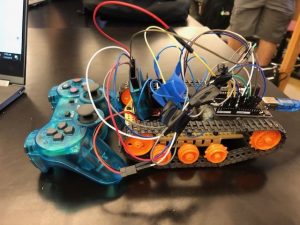
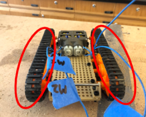
Figure 1: My finished project and PS2 controller
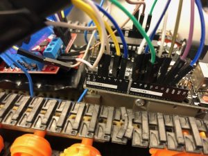
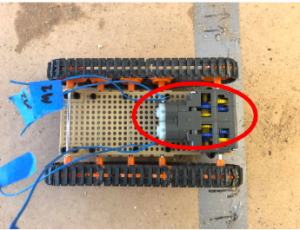
Figure 2: Close up view of my wiring
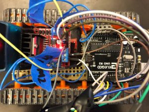
Figure 3: A bird’s eye view of my wiring
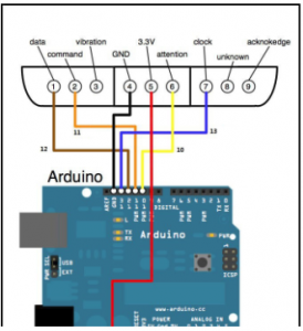
Figure 4: How to wire a PS2 controller to an Arduino via https://docs.google.com/document/d/1kleM-WRweIVeX3IYKvp8itfqTThXyuX70dQfaHcrsWM/edit?ts=5d307f8d#
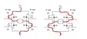
Figure 5: Picture of how the H-bridge works
First Milestone
My first milestone was to complete the chassis for the tank. What it does as of right now is move with the gearbox. How I assembled it was that, first I made the gearbox, then I assembled the chassis. After the chassis was complete, I added the wheels and the tank tread. The way it moves is that there are 10 wheels. 2 of the wheels are connected to the gearbox. Around the wheels are tank tread, when pushed forward, the wheels turn, making the tank tread turn as well, which makes the whole tank moves. Connected to the gearbox are two motors, which are going to make the gearbox move. Connected to the wheels are axles, all but two of the axles go through the base of the tank. The other two go into the gearbox. Connected to the motors are four soldered wires, two wires connected to each motor, these are going to be connected to the Arduino so that it can receive power from the battery pack.
Images
TV-B-Gone
My starter project was TV-B-Gone http://www.adafruit.com/products/73 . It is a device that turns off most TVs with just the click of a button. When you hold the device in front of a TV, it send out infrequence that turn the TV off. I loved making this because it is really fascinating to use and I can now mess with my family. One thing that I learned is how to solder. I have never done that before and it seems like a crucial part of engineering. Another thing that I learned is that sometimes you need to step back in order to advance. I was really reluctant to restart because I had done so much but then I realized that I would not be able to move forward if I did not restart. I have never really worked this independently on a project and it was a great experience. It really set me up for the main project and I am ready and looking forward to building my RC tank.
Images
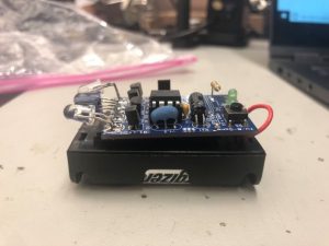
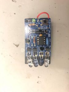
How it works
When the button is pressed, the LED’s flash and turn off the TV. It is powered by 2 AA batteries through a battery pack. An LED is a light-emitting diode that emits light when a current flows through it. A diode is a semiconductor device with two terminals and only allows current to flow in one direction. The blasters on the remote are IR LED’s which is most common for remotes. IR stands for infrared. Infrared light is a type of light with electromagnetic radiation. The reason we cannot see infrared light is because the wavelengths are longer than visible to the human eye. So you will have to check if it is working through a camera. There is one button which is supposed to act as a turn off button for the TV. There is also a resonator that runs at 8.0MHz. The resistors control the power of a micro-controller pin and are designed keep currents under 100mA. The way it works is that the small computer chip in the device mimics the frequencies of all TVs in its database. The TV sees it and emits the light and it turns off.