
RC Tank
My name is Daniel, and my project is the RC Tank. The tank has two treads that are controlled by the joysticks on a PlayStation 2 controller, and RGB NeoPixel lights on the bottom that are controlled by the buttons on the controller. It was a lot of fun to build, and I learned a lot about software and hardware in the process.
Engineer
Daniel N
Area of Interest
Aerospace Engineering
School
SAR High School
Grade
Rising Junior
Reflections
During my time in BlueStamp, I have learned many important things. I learned about motor drivers, controllers, Arduino, and NeoPixel. I researched how they work and learned to write code for each of these components. I grew very familiar with Arduino and the code used with it, and I am positive that I will make more projects on my own with Arduino. This program has given me an insight into the world of engineering, and I think that this is what I would like to pursue as a career.
The most important thing that I learned at BlueStamp was problem solving. Whenever there was an issue or a bug at any point in my code or in the process of building the tank, I had to figure out how to fix it by myself. This is a skill that is important not only for engineering but in all aspects of life. Of all the things that I am taking away from this program, this skill is definitely among the ones that I will remember for a long time.
Lastly, BlueStamp was really fun. I had amazing time, and I enjoyed every second of the creation of my project. I hope I can participate in other programs in the future like this one, and I would encourage anyone with even the slightest interest in engineering to do BlueStamp.
Final Milestone
Final Schematic

This is the final milestone of my main project, the RC Tank. I switched the controls of the tank on the controller so that the analog sticks control the treads. When the right stick is pushed forward, the right tread moves forward, and when it is pushed backward, the tread moves backward. The same is true for the left stick and left tread. The tank is moved forward by pushing both sticks forward, and moved back by pulling both sticks back. The speed of the treads can also be controlled by the joysticks; when they are moved a little, the motor speed is low, and the speed increases as the sticks are moved farther from the center, either up or down. I accomplished this by first mapping the Y values (up and down) of the two sticks to a range of -255 – 255. I wasn’t concerned with the X values, so I didn’t map them. After mapping the Y values, I wrote some code that looks this this:
if (map(ps2x.Analog(PSS_LY),0,255,-255,255) > -1){
motorA.backward();
motorA.setSpeed(map(ps2x.Analog(PSS_LY),0,255,-255,255));
}
This code tells the Arduino to turn the left motor (represented by motorA) backward if the Y value of the stick is above -1. I used -1 specifically because that was the value that the stick was outputting when it was centered. Additionally, the setSpeed function tells the motor to spin at a speed that is equivalent to how far back the stick is pulled.
Here is the rest of the code for the left motor and left stick:
if (map(ps2x.Analog(PSS_LY),0,255,-255,255) < -1){

motorA.forward();
motorA.setSpeed((map(ps2x.Analog(PSS_LY),0,255,-255,255)) * -1);
}
if (map(ps2x.Analog(PSS_LY),0,255,-255,255) == -1){

motorA.stop();

}
The second “if” statement essentially does the reverse of the first one; it tells the Arduino to spin the motor forward if the stick is pushed forward, and at a speed that is equivalent to how far forward the stick is pushed. The last section states that if the sticks are centered (they are not being moved), the motor will stop. There are three more “if” statements for the other stick and motor.
After successfully testing the tank to make sure everything was working, I decided to make a few modifications to the tank. I started by programing a few commands for the tank’s movement to different buttons on the controller. For example, the R1 and L1 (right and left bumpers) spin the tank in a circle by turning one tread forward and the other backward.
I then added some NeoPixel RGB LED strips to the tank. I did some research on how to control the color of the NeoPixels and how to make some awesome patterns and animations. I programmed the face buttons to change the color of the lights, and the R2 button (right trigger) to initiate a really cool rainbow light pattern animation. The start button turns the lights off. I mounted the NeoPixels on the bottom of the tank so they reflect off the floor for an awesome light effect.
NeoPixel Light Strip


Tank Controls

Second Milestone
For my second milestone, I connected a wireless PS2 controller to the tank to allow the tank’s movements to be controlled by the controller. Before programming the Arduino to allow the motors to be controlled by the controller, I first did some research on how the controller worked. There is a wireless receiver that connects to the Arduino, so I found out what each pin was for and wired it to the board. I then downloaded a PlayStation 2 Controller library from Bill Porter’s website and uploaded the library example to the Arduino. When the serial monitor for the board was opened, it was supposed to display certain information based on which buttons were pressed on the controller. However, it didn’t work when I tried it. I attempted to debug the code and adjust the wiring, but nothing seemed to work. I decided to try one last thing: I found a new controller and wireless receiver. When I plugged in the new receiver and connected the new controller, everything worked fine. In fact, the old controller worked with the new receiver, which meant that the problem was just that the first receiver was defective. After making sure the controller and receiver were working properly, I used a zip tie to attach the receiver to the front of the tank. I then proceeded to write a code to the Arduino that would allow the buttons of the controller to turn the motors and steer the tank. There was a lot of troubleshooting and debugging involved, but eventually I produced a successful result. The code that I wrote allows the tank to be controlled with the four buttons on the front right of the controller. Triangle makes the tank move forward, X makes the tank move backward, and the square and circle buttons turn the tank left and right, respectively. Here is my Milestone 2 Code. In addition to the utilization of the controller, I made a few other small changes to the tank itself. I used a few small zip ties to secure many of the wires so they would be organized and not tangled about the tank, where they could potentially get caught in the treads. I also added a switch at the back of the tank so that the entire tank could be turned on and off without having to plug and unplug the battery. I did this by soldering the switch to the wire connecting the power terminal of the battery to the power terminal of the motor driver and then using some electrical tape to secure the switch to the back of the tank, along with the wires for the battery. Finally, I used a small strip of Velcro to mount the battery to the top of the gearbox. Some potential modifications that I would like to make are to allow the motors to be controlled by the analog stick on the controller so that the speed of the tank can also be controlled. I would also like to add a small laser turret to the front of the tank.
Tank with PS2 Controller and Receiver

PlayStation 2 Controller

Updated Schematic (with receiver and switch)

First Milestone
The first milestone of my main project, the Remote-Controlled Tank, was to assemble the tank and get the motors to turn. The main body of the tank consists of a chassis with ten wheels and two treads.There is a double gearbox mounted on the back with two motors that move the treads of the tank. The motors are controlled by an Arduino Uno micro controller and a L298N Motor Driver, and the tank is powered by a 2000 mAh 6V NiMH (Nickel Metal Hydride) battery pack. Before starting to build the tank, I researched how to use the Arduino and motor driver to turn the motors and control their speed and direction. I also downloaded the L298N library from Andrea Lombardo’s GitHub page. I began the assembly of the tank by building the double gearbox with a 114.7:1 gear ratio. I then assembled the chassis and mounted the gearbox onto the base plate of the chassis. This was quite difficult because the instructions included were hard to follow, and I had to figure out myself how many of the parts fit together. I used some small plastic posts and screws to mount the Arduino to the chassis, and I used another post to secure the motor driver to the Arduino. I then wired the motors to the driver and the driver to the Arduino. To make sure everything was working properly, I wrote a simple code that made the motors turn for one second and then stop. At first, it didn’t work, and after trying to fix the code and the wiring, I discovered that the problem was actually with the way I was giving power to the motors. I had the battery pack wired to the Arduino, and then power went from the Arduino to the driver. However, since the Arduino can only output a maximum of 5V, the motors weren’t getting enough power. To fix this issue, I wired the battery directly to the motor driver, and then rerouted the power from the driver to the Arduino through the VIN pin on the Arduino. When I tried uploading the code again, it worked perfectly. My next step in the project is to connect a PS2 wireless controller to the Arduino and figure out how to write code to the board that will allow the motors to be controlled by the controller.
Fully Assembled Tank

Schematic for the Tank (after fixing power issue)

Starter Project
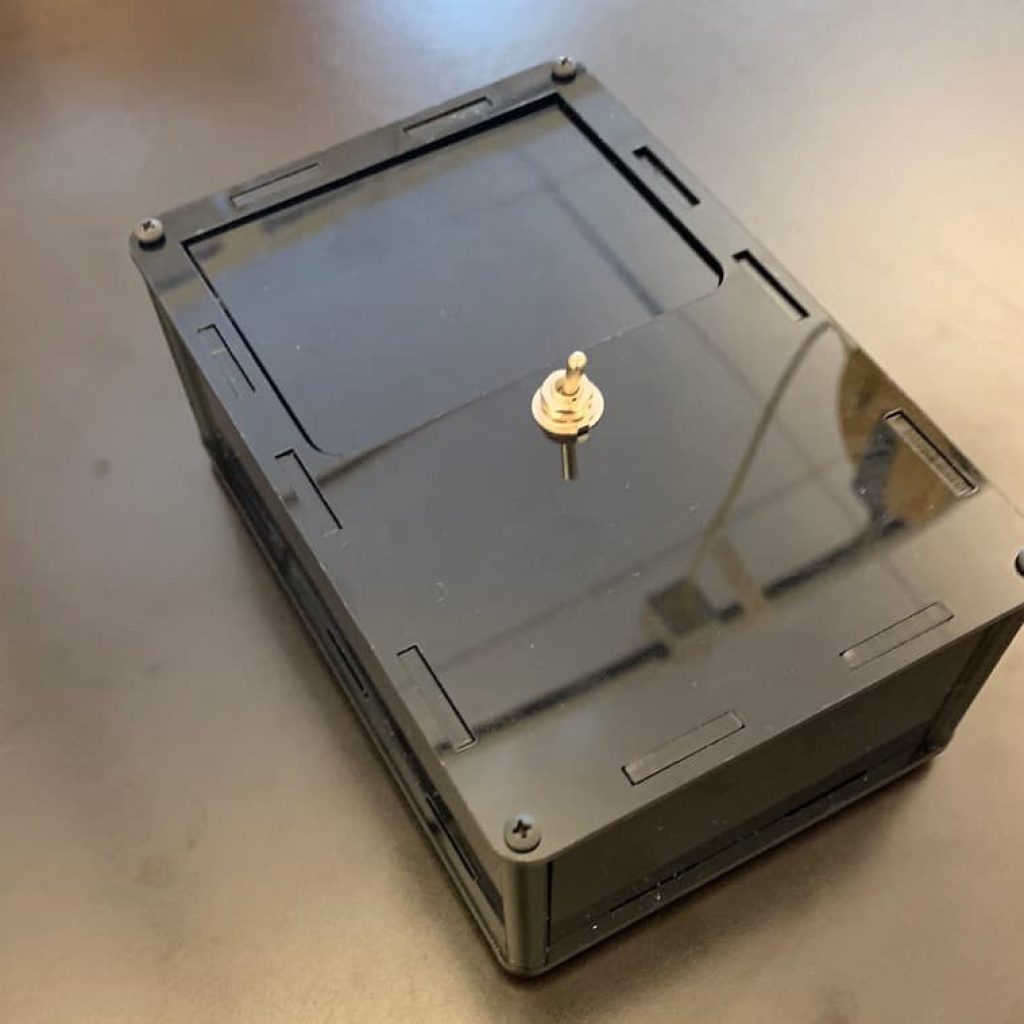
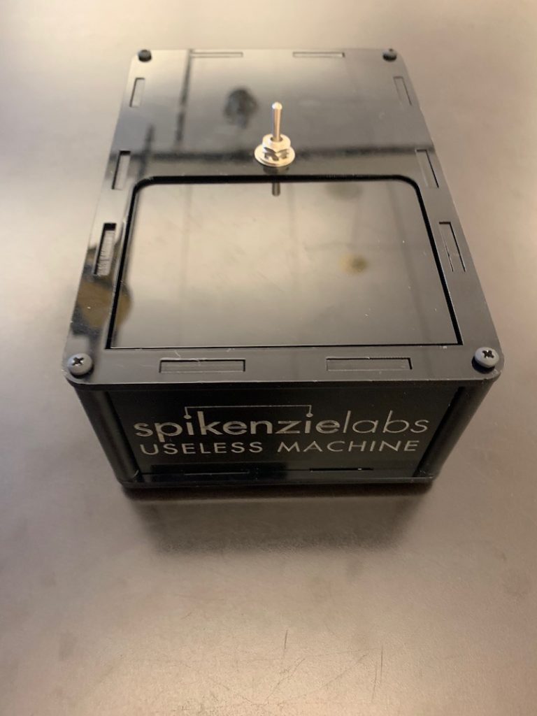
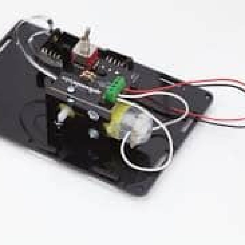
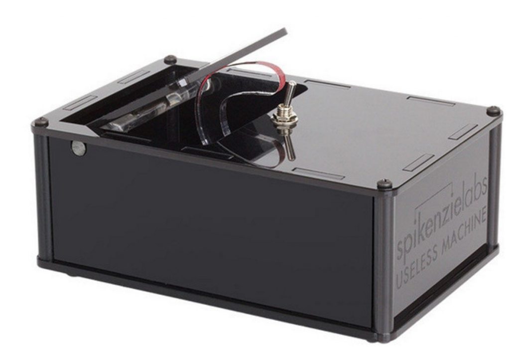
For my BlueStamp starter project, I built the Useless Machine. The Useless Machine is a black rectangular box with a small toggle switch on the top. When the switch is flipped, a small mechanical arm pops out of the top of the box and pushes the switch back to its original position. The arm then retracts back into the box, and thus the machine is reset. This process can be repeated again and again, and since it accomplishes nothing, the machine is “useless.” Nevertheless, it was a good introduction to soldering and basic electronic circuitry, and an enjoyable build as well. I assembled the machine using instructions that I found on the website of the company that makes the kit, SpikenzieLabs. I faced a few issues while building the machine. One was that I did not solder the motor and battery terminals properly to the PCB, so I had to desolder and resolder them. I also had some trouble tapping (widening the screw holes) the plastic corner posts, so I decided to wrap some rubber bands around them so I could grip them better and properly insert the screws. All in all, however, the assembly went smoothly, and it was completed within the first day of the program.
How it works
The outer box of the machine is made of seven black acrylic pieces and four plastic corner posts. A PCB (printed circuit board), a switch, a motor, an acrylic arm, a bicolor LED, a 100Ω resistor, a 220Ω resistor, and a snap switch comprise the inner workings of the machine. It is powered by a battery pack that houses three AAA batteries.
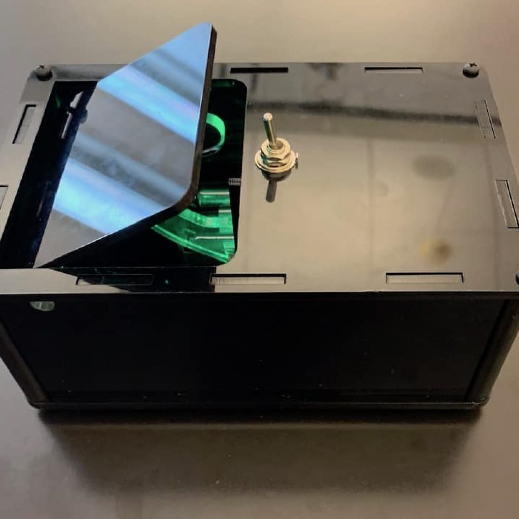
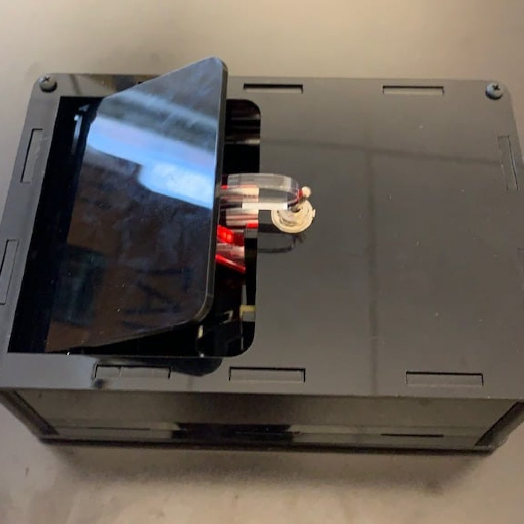
When the main switch is flipped, the circuit is closed and electrical current flows from the battery pack to the bicolor LED and to the motor. The LED turns green and the motor turns counter-clockwise, swinging the small acrylic arm up and out of the flap on top of the box. The arm moves toward the main switch and pushes the switch back. This causes the current to change direction and turn the motor the other way, swinging the arm away from the switch and back into the box. The change in direction of current also changes the color of the LED to red. There is a small snap switch inside the box that turns the motor off when a small protrusion on the bottom of the arm pushes against it. This prevents the arm from over-rotating on its way back into the box. It also turns the LED off, and the system is reset, ready to repeat itself again when the switch is flipped.
USELESS MACHINE SCHEMATIC
