RC Robot Tank
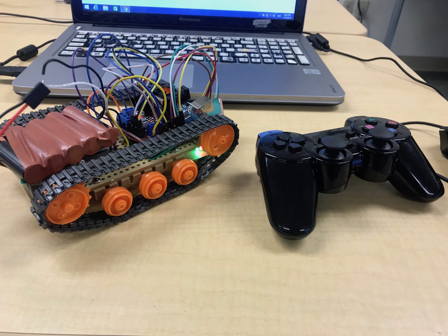
I produced a remote controlled robot tank that utilizes an Arduino UNO. The robot tank consist of two DC motors and can be operated by a wireless PS2 controller
Engineer
Daniel C
Area of Interest
Mechanical/Aerospace Engineering
School
Cupertino High School
Grade
Incoming Sophomore

Second Milestone
For my final milestone I connected the ps2 wireless receiver to my arduino. Then I wrote a code to put in the arduino which allowed me to control the tank using the ps2 controller. The first thing I did was connect my ps2 wireless receiver to my arduino. At first, I couldn’t fit my jumper wires into the wireless receiver so I decided to solder them on instead. To connect the receiver with the arduino, you have to use 6 out of the 9 pins. The first pin is data, which is the master line that sends data from the controller to the receiver. The second pin is command which sends data from the receiver to the controller. The third pin is for vibration which we don’t need. The fourth pin is the ground. The fifth pin is the power which can vary from 5V to 3V. The sixth pin is attention. This is used to get the attention for the controller, preparing for the connection. The seventh pin is clock. The clock pulses which synchronizes data transmission generated by the master line. The eighth pin has no connection which we don’t need and the last pin is for acknowledgment which we also don’t need. So overall, we need pins 1, 2, 4, 5, 6, 7. After soldering the ps2 receiver to my arduino, I started coding my arduino. First, I needed to download the ps2x library in order to connect arduino to controller. After that I started writing my code. After uploading my code to the arduino , I had one problem. The problem was that if I left the controller untouched, the tank would go forward, but when I pressed the button that was suppose to make it go forward, the tank would stop. So basically I had the forward keys and stop switched in the code. I solved this problem by setting my motors to different buttons on the ps2 controller. So now if I press the buttons on the ps2 controller, in will move on command.
First Milestone
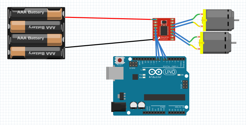
For my first milestone of my main project, the RC robot tank, I constructed the chassis of the robot as well as made my gears turn on using the Arduino. I started off building the chassis of the tank which included the gearbox, the universal plate, and the track and wheel set. I started building my gearbox which included two DC motors, gears, and two shafts. Then, I used the dremel to drill two holes in the universal plate to attach my gearbox. Then I connected one wheel to each of the shafts which made sure the rest of the wheels were turning. After building the chassis of my robot, I started to connect my Arduino to the L198N motor driver. After wiring the Arduino and motor driver together, I soldered the wires to connect the motor driver with the motors. Then I tested my motors through a simple code to make sure the motors would run. After all the uploading my code to the Arduino, I connected my 6V battery to the Arduino which activated the motors. Although my project ended up working, I had many challenges along the way. My first challenge was that I did not use the wire strippers to expose the copper which resulted the electricity flow to stop. My second problem was that I connected my 6V batteries to the 3.3V slot which fried my Arduino and computer.
Starter Project
For my starter project, I chose to build the Simon Says game. I picked the Simon Says game because it would introduce me into soldering as well as learn different electrical components to the machine. There are two switches on the Simon Says game. One to power the device on and one to activate the sound. The machine is powered by two 1.5V alkaline batteries which can power the lights and the noise. On the bottom of the board, there is a microcontroller, which is the control system of the whole device. The microcontroller contains processor core, memory, and programmable peripherals. There is also a black cylinder called a piezoelectric buzzer. The piezo buzzer makes sounds when voltage enters, causing crystal or ceramic form of the piezoelectric element to deform. There are also two decoupling capacitors which filter out the AC signal from the DC signal, creating a purer DC signal. Another component that my machine had was the 10K resistor. The resistor’s job is to reduce current flow as well as lower the voltage. I have learned a lot through this project such as soldering and also knowing what the components such as decoupling capacitor, microcontroller, and the piezo buzzer does. I took a long time to research the parts of this device as I have not used many of those parts.


