Three Jointed Arm
A robotic arm with three joints and a claw, capable of moving objects.
Engineer
Daniel B
Area of Interest
Mechanical and Software Engineer
School
Gunn High School
Grade
Incoming Junior
Final Product
Third Milestone
Video
Math for Keeping Claw Perpendicular
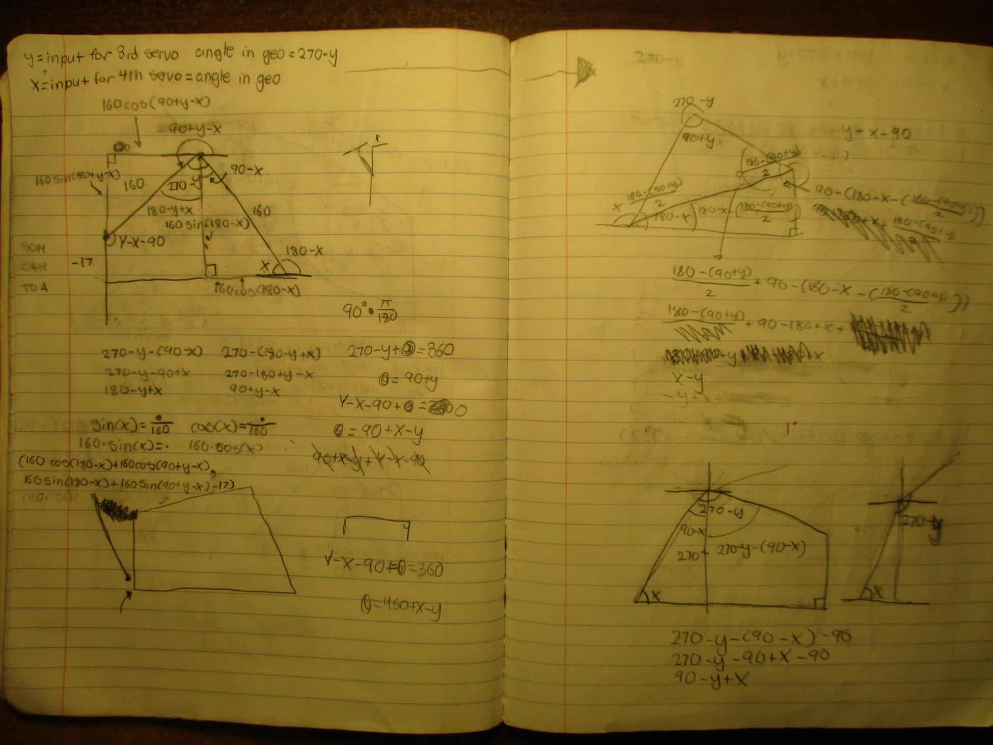
Summary
Second Milestone
Video
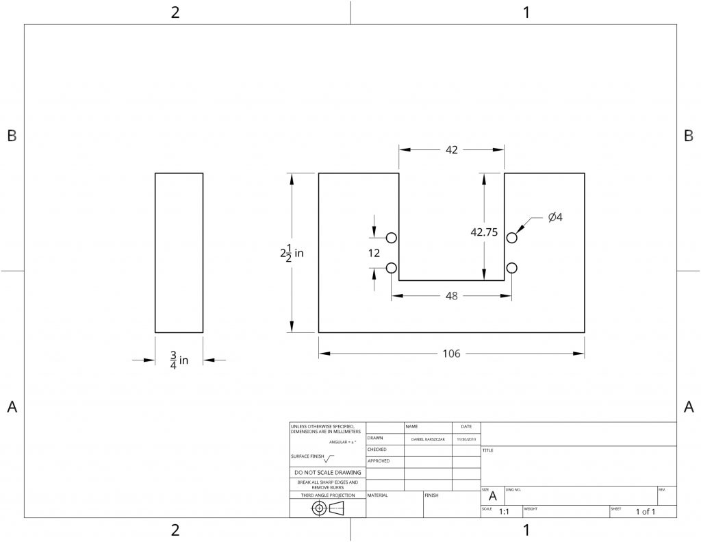
Part Drawings
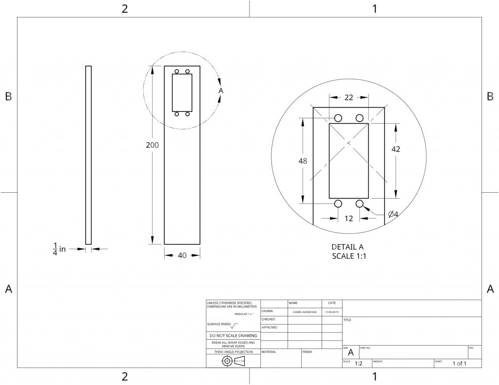
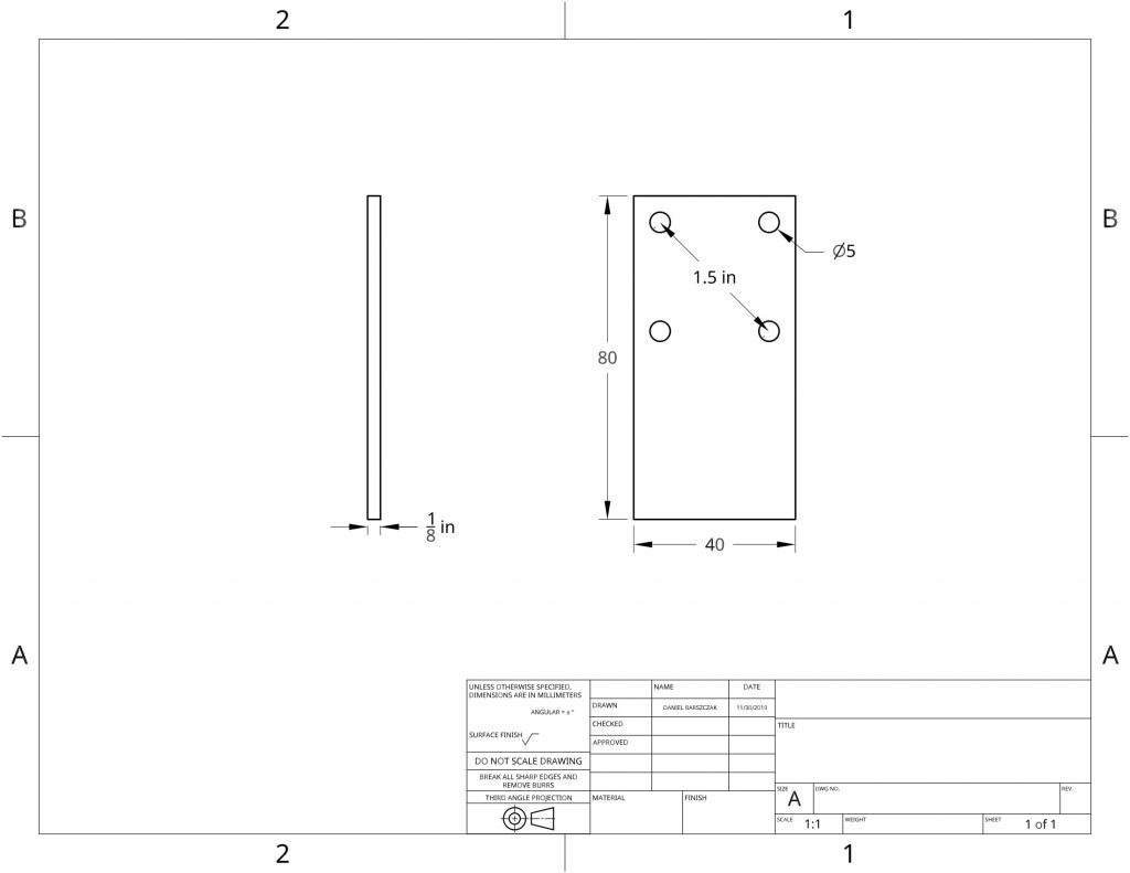
Summary
First Milestone
Video
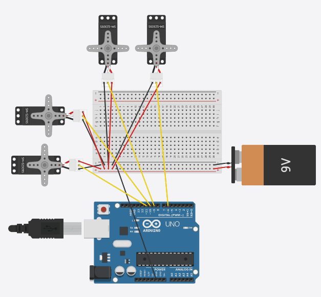
Circuit Diagram
Summary
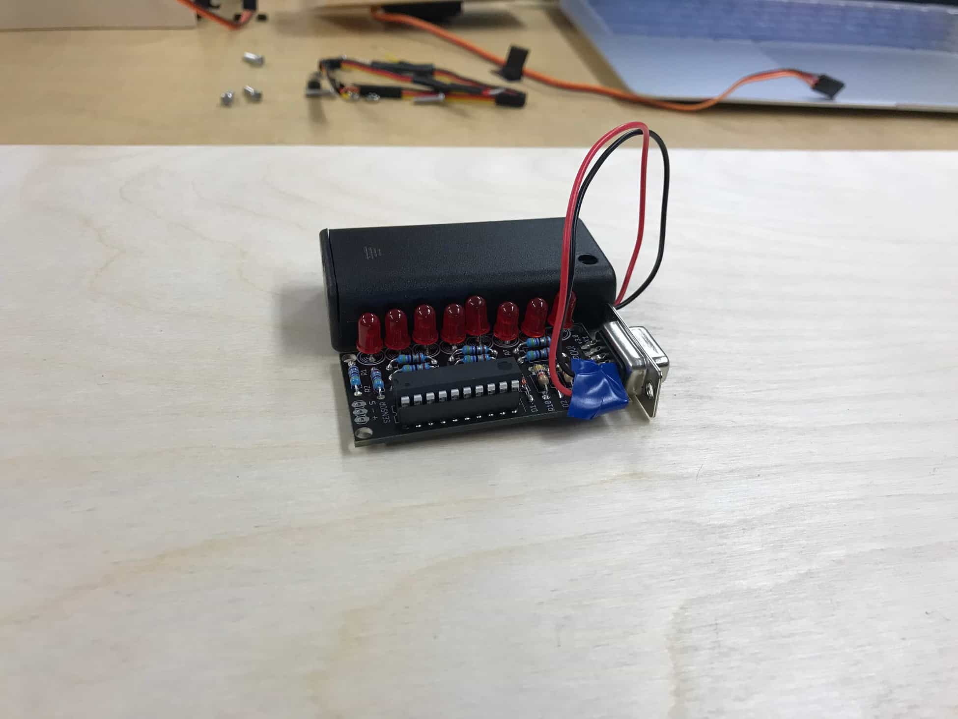
MiniPOV
Video
Starter Project