Hovercraft
The Hovercraft operates using two powerful fans, one pointed towards the undercarriage of the vehicle to inflate the skirt and provide lift, and the other pointing towards the back of the hovercraft to provide thrust. The fan on the back is mounted on a servo motor with a limited range of motion to allow for turning.
Engineer
Cole M
Area of Interest
Mechanical/Aerospace Engineering
School
Ardsley High School
Grade
Incoming Senior
A short demonstration of the Hovercraft in action… (Keep in mind that this video was taken on a slanted driveway and the hovercraft is very difficult to maneuver).
Third Milestone
For my third milestone, I troubleshot problems preventing the hovercraft from maneuvering properly and finalized the prototype, making it fully functional. My first problem arose at the end of my second milestone when the battery shorted due to improper wire insulation. After I checked that the battery was safe to use and that the wires connecting the battery to the ESC were properly insulated, I tried it out and it worked perfectly. Despite my troubleshooting, that same problem occurred again near the end of the third milestone. Another one of the most aggravating and time consuming problems that I encountered was evening out the weight distribution to make sure that the hovercraft did not drift forward or to the side. I did two things to fix this, the first was I partially covered the holes leading into the skirt of the hovercraft to direct the airflow in a way that would stabilize the vehicle. The second (and more effective) action I took was to position the battery pack on the hovercraft opposite the direction it was drifting. I ran into other small problems along the way such as configuring the receiver and learning how to program the transmitter (controller) to my specifications.
Second Milestone
For my Second Milestone, I began construction of the prototype. Before I could start building the prototype, I first needed to connect the second fan to the battery pack. To do this, I soldered an ESC to the second fan, and then cut and soldered that ESC to the same battery pack that the first fan was connected to. I used a multimeter to ensure that the output of the battery would be enough to power both fans. Once connected to the battery, I connected both of the ESC’s and the servo motor to the receiver so that I could control them using the transmitter (controller).
Building The Skirt
The skirt of the Hovercraft is what inflates to produce a high pressure environment which allows the hovercraft to rise above the ground and glide with relatively low friction and theoretically on any surface. In order for my skirt to function, it needed to be air-tight so that it could properly inflate. The easiest and most effective way that I could think of doing this was to use a single, long, strip of nylon fabric instead of multiple pieces all glued together. First I cut out two identical pieces of a cardboard frame, to the first piece, I cut four holes evenly spaced along the board to make sure that air going into the skirt was not only flowing to the area directly beneath the fan. To the second piece, I hollowed it so that it was just an outline of the frame. I super-glued the nylon strip in between these two frames, and that is how I created a structured and airtight skirt for my vehicle.

First Milestone
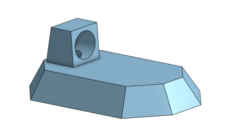
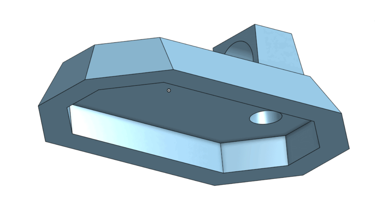
My First Milestone for the Hovercraft was to create a CAD design of the chassis to aid me during the construction of the prototype and final project. I marked down all of the dimensions of the frame given on the CAD program and used them to begin construction of my prototype. Additionally, I set up and tested the motors to make sure that they were functional before moving on to the prototype.
Testing The Motors
To safely test the motors, I first needed to secure them in a rigid frame. I made a cardboard frame with super glue and cut the cardboard to the right dimensions to ensure that the fans would not be able to break loose. Before fitting the motors into place, I soldered one of the motor to the ESC (electronic speed controller), and then the ESC to a Lipo battery connector so I could easily connect and disconnect the battery from the ESC when I need to charge it or in case of an emergency. I connected the motor and the servo to the radio receiver and then paired the receiver to the transmitter (the controller). After that, I was ready to test.
