A little about me:
Hello and welcome! My name is Coby, and I’m a rising sophomore at the Urban School of San Francisco. I have been interested in engineering for the for the past couple of years, and especially the computer science aspect. I am also interested in bioengineering, although I didn’t specifically focus on that in this program.
I think that Bluestamp provided the perfect opportunity for me to explore and learn the basics of engineering. In the past, I had touched lightly on coding, but after this program I have a much more solid grasp of programming logic and a basis for mechanical engineering which I will use in my own projects in the future. As well as all of the intelligent people I met, I think that I’m taking away a newfound sense of independence from this program.
Final Project: Motion Controlled Snake Game
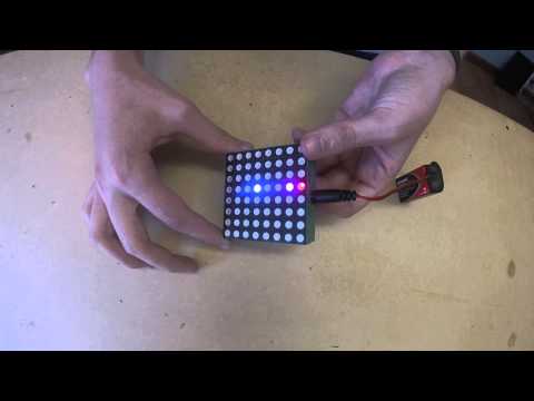
This is my final project: an acceleromter controlled snake game. The code is complete, and the matrix-value-LED-lighting system functions well. The menu transitions into the game smoothley, and the game is tweaked to be challenging but not impossible. The case is solid and looks good as well. I am very satisfied with the outcome of this project.
My snake game runs on a rainbowduino, a variant of arduino, and is displayed on an 8x8 LED matrix, with a 9v battery for power. It receives a positional input from an accelerometer, and interprets that into movement for the head of the “snake” which is followed by the segments of the body. When the head encounters a piece of food, the snake grows one segment and a new food pixel is randomly generated.

Case with board and accelerometer visible

Case with battery and LED matrix visible

Complete case
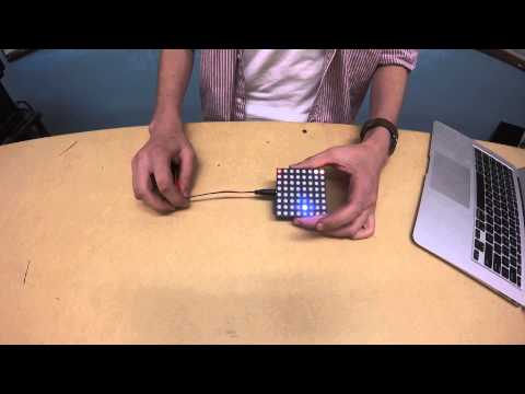
For my third and final milestone, I made a case for the game out of particle board and hot glue. I was originally going to either 3d print a case or cover a case in leather, but the basic particle board actually looked pretty good, and had a lesser chance of overheating. I also modified the 9v-to-barrel-jack adapter so it would fit in my case better.
Some future modifications I could add on to this project would be other games using the same basic accelerometer principle, such as a basic space invader game.
Documentation
I based this project off this instructables project.
This is the code I wrote for my project.
Bill of materials:
| Description | Vendor | Part Number | Qty | Cost | Link to Where to Purchase |
| 8x8 RGB LED Dot Matrix – Compatible with Rainbowduino | Seeed | LED204A5B | 1 | $9.90 | http://www.seeedstudio.com/depot/60mm-square-88-led-matrix-super-bright-rgb-p-113.html?cPath=34_77 |
| Rainbowduino LED driver platform – Atmega 328 | Seeed | ARD127D2P | 1 | $24.90 | http://www.seeedstudio.com/depot/rainbowduino-led-driver-platform-atmega-328-p-371.html?cPath=6_7 |
| Grove – 3-Axis Digital Accelerometer(±1.5g) | Seeed | SEN21853P | 1 | $9.90 | http://www.seeedstudio.com/depot/grove-3axis-digital-accelerometer15g-p-765.html?cPath=25_26 |
| 9V to Barrel Jack Adapter | Seeed | POW05231B | 1 | $0.50 | http://www.seeedstudio.com/depot/9V-to-Barrel-Jack-Adapter-p-1481.html |
I also used a basic on/off switch and some particle board for the case. The particle board I used was (in centimeters0:
1 8x6 (base-plate)
2 8x4 (side pannels)
2 8x2(inserts for the board to rest on)
1 4x6 (back-plate)
1 4x6 (front-plate with a hole for the switch)
1 2x4 (removable plate to cover wiring next to board)
Milestone 2: Acceleromter
For my second milestone, I soldered the accelerometer to the board and hot glued it on. The game now functions with tilt control, and is integrated into one piece. I wired the the SDA, SCL, 5 Volt, and Ground Pins. I used the positional input from the acceleromter, which uses crystal structures to determine the acceleromter’s position in space. I chose this instead of acceleration because it is easier to set up and allows for easier control right off the bat.

Accelerometer
This step was fairly difficult, because I had to remove a part of the accelerometer to get it to fit in between my board and LEDs, and in the process damaged some leads that I needed to connect. To fix this, I had to solder wires directly onto the chips on the board, which ended up working out.
To finish my project, I need to add a menu to my game and make a case for it.
Milestone 1: Base code
For my main project, I decided to write my own code for the snake game from scratch instead of using the sample code on the Github. I didn’t understand most of the advanced functions in the example code, but I thought I could build the same thing with the simpler functions that I had already learned. The strategy that I ended up with assigned values to spaces in a matrix (an array of arrays) which represented the real board of LEDs, and lighting up or leaving blank pixels based on the values.
For my first milestone, my goal was to put the mechanical components together, and move a pixel around the LED matrix in a pattern. However, as of the time of the first milestone, coded a snake with a body that follows the head, food that is randomly generated and grows the snake when eaten, and a game-over state when the body touches the head. The snake also can’t double back on itself and there is a small module that moves the snake randomly. Mechanically building the setup was very simple, and just involved connecting the matrix to the rainbowduino. The coding for the game was more difficult, and I ran into difficulties with getting the pre-coded libraries to work on my rainbowduino, as well as with the built in random function in the arduino code.
For my next milestone, I will need to connect the accelerometer to the game, and get that to function optimally.
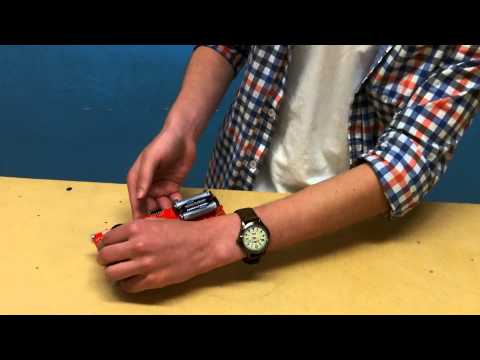
Starter Project
For my starter project, I made a Gram Piano from sparkfun. This is an octave piano that uses a microprocessor to interpret touches into music. In the project, a battery pushes power through the PCB (printed circuit board), through capacitive touch sensors, to a microprocessor , and from there into a speaker. It uses resistors to regulate the flow of electricity through the board to keep the circuit from shorting, and uses capacitors to smooth out the voltage before the microprocessor. The microprocessor then checks each capacitive touch sensor, and if one is in contact with an electric field (e.g. a finger) it plays the tone corresponding to the note multiplied by the setting of the potentiometer to produce different octaves. It was mainly a soldering project, so I learned how to solder as well as the functions and uses of capacitors, capacitive touch sensors, resistors, microprocessors, and potentiometers. I also learned how to desolder, as I initially mis-soldered one of the resistors.