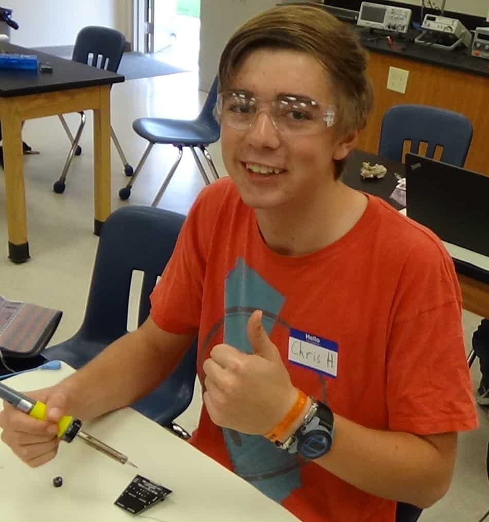
Introduction: My name is Chris H. and I am a rising senior at Homestead High School. I worked on the SparkFun Digital Metronome for my starter project and the Sound into Light Show circuit for my main project. I have learned a lot of things with this program like how to construct a physical circuit, how to code in C and C++, and, most of all, perseverance and patience are key traits needed for engineering. I say those traits because I have learned to use them well with my main project because at times, I would be troubleshooting my project and I wouldn’t be making any progress. I would definitely get impatient with the project and start making changes that wouldn’t make sense. I would then take a “step back” and take a real look at what I needed to fix and address the problem and then make it work. The projects I worked on were really fun, even though I had difficulties with them because I felt passionate about fully building them and feeling the satisfaction of making the project fully.
Final Milestone/Project: Circuit in Box and Modify Code
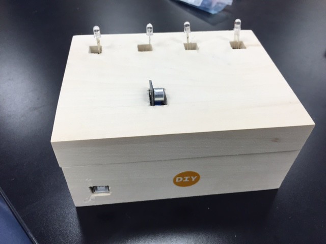
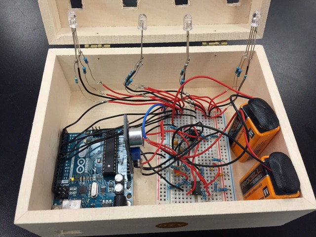
This final milestone for my Sound into Light Show project features a new and improved code for the circuit and a box for the circuit to look more appealing for the user. I have simplified the new and improved code, so it is more straightforward with its approach to make the circuit act properly because before this milestone, the code was too complicated and made the circuit very sensitive to the sound input it was getting from the microphone. I have also put the circuit in a box to make it look more appealing to the user, since the user doesn’t want to see a bunch of wires and LEDs only supported by wires and resistors. The box has openings for the LEDs, the microphone circuit, and the USB port for the Arduino, so I can still program the Arduino as I continue to modify this project to make it the best it can be.
This milestone was also a learning experience for me because as I was making the code for this milestone, I experienced a lot of difficulty making the different-colored LEDs fading while coexisting with the others. I eventually learned how to make code, so that my LEDs could fade with multiple colors at once. I also learned how to drill holes and cut gaps for my box, so the components that I want to be shown are shown properly to the user. Even though I had difficulty with this project, I really liked this project all the way through and building it was super fun and I want to continue building it further by making the case seem more professional, moving the circuit to a PCB (Printed Circuit Board) (see glossary), and put on more LEDs to the circuit to make it more vibrant.
Here are the schematics that I was inspired by to build this project, code I eventually modified, and bill of materials I used for making this project:
Schematic (Main Part) – http://www.instructables.com/files/orig/F5U/ZUKM/GHZ75FHE/F5UZUKMGHZ75FHE.jpg
I made some changes to this circuit, like:
- The first part of the circuit with the LM386 Audio Amplifier is already implemented in the microphone.
- No potentiometer (the microphone has a potentiometer on it)
- I used 15K Ohm resistors in place of the 560 Ohm resistors and a 27K Ohm resistor for the 2K Ohm resistor.
- I also replaced 3.3K Ohm resistors for the 1K Ohm resistors connected to the 0.1 uF capacitor and in parallel with the filter and a 6.8K Ohm resistor for the 20K Ohm resistor.
- I finally substituted 820 Ohm resistors for the 10K Ohm resistors and a 1.5K Ohm resistor for the 1.12K Ohm resistor.
Schematic (Detailed Battery Part) – http://www.instructables.com/files/orig/FE0/M5PR/GHFJX8HN/FE0M5PRGHFJX8HN.jpg
Code – Sound_into_Light_Show_Code
Bill of Materials – https://docs.google.com/spreadsheets/d/1OCV0ZbOzCIjVZddj6-tLNw9ulSI6wrL-DW4xbnkpeCs/edit?usp=sharing
Milestone #2: Fully Functional Circuit and LED Pulse
This is my second milestone for my Sound into Light Show circuit. My circuit is fully complete now with three more RGB LEDs (see glossary). I have soldered on wires and resistors to the RGB LEDs to make them free-standing RGB LEDs and make sure that they have the right amount of voltage passing through them. These free-standing LEDs will make them easily maneuverable, so I can position them correctly to fit in the case I will put it in. I have also added a slight pulse to the LEDs to make it feel more in tune with the music that it is listening to. I have done this by modifying the code to have the LEDs respond like they should with the original code, but then fade through a pulse width modulation (PWM) (see glossary) function. I have made this pulse function customizable by being able to increase or decrease the starting brightness, amount of brightness it decrements by, and the frequency of the brightness decrement.
As I went through this milestone, I experienced a little bit of difficulty trying to apply the correct and proper pulse because I needed to learn how to code the PWM function into my code. Even though it was difficult, this was really helpful because it helped me further my understanding on how to code in the C/C++ programming languages. The soldering of the wires and resistors onto the LEDs also helped me further my understanding of soldering because it was a different style of soldering rather than the traditional soldering with a hole in a board and a wire placed through it. This milestone was really fun because of the soldering and the modifying of the code for the Arduino Uno (see glossary).
Milestone #2 Code – SoundintoLightShow_Code2
Milestone #1: One LED Fully Functional
This is my first milestone for my Sound into Light Show project. This project converts sound input and translates it into a electrical signals that make a LED light up. This circuit is made up of three main circuits: the microphone circuit, the amplification circuit, and the filter circuits. The microphone circuit takes sound input and translates those into electrical signals that the circuit can understand. These electrical signals can be adjusted through a potentiometer, which increases or decreases the sensitivity of the microphone. The amplification circuit uses one operational amplifier (op-amp) (see glossary) to amplify the signal coming from the microphone to make sure that the circuit can clearly understand the signals coming from the microphone. This amplified signal then travels through three different Sallen Keys band-pass filters (see glossary), which are on three other op-amps and they let three different frequencies of sound pass through the circuit, which are 110 Hz (bass guitar), 440 Hz (electric guitar/background vocals), and 1760 Hz (vocals). These band-pass filters pass the electrical signals to the Arduino Uno (see glossary), which interprets these signals through code that decides whether to turn on the color of the RGB LED (Red, Blue, and Green Light Emitting Diode) (see glossary) that is associated with the certain frequency of sound. The red LED is associated with the 110 Hz frequency, the green LED is associated with the 440 Hz frequency, and the blue LED is associated with the 1760 Hz frequency.
At first, I thought this project was going to be easier than I thought, but I encountered a lot of difficulty with building this project. I mainly experienced obstacles through the RGB LED because at times it would not turn on or one LED of the three LEDs would stay on the entire time, not reacting to sound at all. I fixed this problem by looking at the circuit and checking if the circuit was put together properly and it was not put together properly, so I had to change the circuit to make sure that it was set up properly and it then worked properly and reacted to sound creating an awesome light show. This project really helped me learn a lot about electrical circuit set up, troubleshooting problems, and building band-pass filters.
Milestone #1 Code – SiLS_Code1
Starter Project: Digital Metronome
My starter project is the digital metronome. A metronome is a device that provides a tempo for musicians at a selected frequency of beats per minute (bpm). This metronome has a tempo range of 1 bpm to 299 bpm and also displays the tempo being provided by metronome using LED displays. It also provides a sound, from the speaker, when the beat occurs, so the user knows when the beats occur. The metronome uses buttons to either increase/decrease the amount of bpm the metronome is operating at. This project was a really interesting experience because it was my first time soldering and it was difficult at first, but I eventually got the hang of it. It also helps me because I am a percussionist, so I need to be at the right tempo with everyone else in my percussion section.
Glossary:
Arduino Uno- A device that uses many sets of micro controllers (hardware) that are programmable through a computer (software) and uses a mix of the C and C++ programming languages.
Operational Amplifier- a voltage amplifier that takes two voltage inputs, takes the difference of the voltages, then applies the set gain the op-amp has to amplify, so the circuit can function properly.
Printed Circuit Board (PCB)- A type of a circuit board that has the circuit components needed for the circuit to function already implemented into a set of conductive copper sheets and layers of non-conductive silicon substrate.
Pulse Width Modulation (PWM)- a function to change the amount of voltage an object is receiving by modulating the pulse width, which is the period of time the object is powered on.
Red, Green, and Blue Light Emitting Diode (RGB LED)- an LED that uses the three primary colors of light (red, green, and blue) to make different colors of light.
Sallen Keys Band-Pass Filter- a type of filter that selects certain frequencies of electrical signals and lets them pass through and blocks out other frequencies, so the circuit can function properly.


