
My name is Christina and I am a rising junior at KIPP Denver Collegiate High School. I am interested in LEDs, electrical, and mechanical engineering. For my project I built a LED Jump Rope and and for my starter project I built a Exploding Star Color Organ Kit. I had lots of fun and had many challenges that I overcame.
LED Jump Rope Final
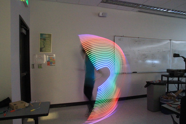
I’m Christina, and this is my final video for my LED jump rope. I attached the slip-ring to the LED strip and put it through the handle. I was able to solder everything together and put them into the jump rope handle. I was able to put the rope through the LEDs strip by cutting some slits in the strip. To make the LEDs light up, the jumper has to move to the pin that connects to the LEDs and battery and vice verse to turn it off or to charge the battery.

I got my code on this link and the zip is Adafruit_NeoPixel
My build materials are here:
https://docs.google.com/spreadsheets/d/1-5u9LGlT7X_5_JFfT3K-9w-M1ea72aByfgjfnQJrYXA/edit
Here is a schematic I made of the wiring:

Green triangle = LEDs
Blue rectangle =Trinket
Gray rectangle = pins for on/off switch
Tan rectangle = charger
I also used the Adafruit NeoPixel Überguide to help me understand the LEDs.
I was inspired by Antonio Ospite.
LED Jump Rope Milestone
I’m Christina, and this is my milestone for my LED jump rope. I was able to program the trinket with the code I had. When it lit up it was not following the code and I found that the problem was the first LED was damaged. I had to remove it so the LEDs could work correctly. The reason why the LED was broken was because I removed the wires in a incorrect order. I had to remove the data wire first, then power, and finally ground.

Exploding Star Color Organ Kit
My name is Christina, and my starter project is a Exploding Star Color Organ Kit. The organ kit uses capacitors, IC 555, IC 4017, red LEDs, green LEDs, yellow LEDs, horizontal trimmer resistors, transistors, resistors, mic, battery snap , and a PC board. First, a sound is received from the microphone which convert a sound wave to an electric signal. The electricity is adjusted based on the resistors which regulate voltage. The voltage goes to IC1, the IC 555, which sends a signal to IC2, IC 4017. The voltage in IC2 will trigger a specific array of LEDs to light up. The voltage will flow into the transistor switch acts like a switch and trigger the LEDs. The LEDs will light up for a certain amount of time depending on if there is another sound from the mic that triggers IC1.
