Sketch-It CNC Plotter

The Sketch-It CNC Plotter takes in G-code to draw a picture. It is capable of drawing images within a 4×4 platform using two stepper motors and one DC motor.

Engineer

Charlie Y.

Area of Interest

Computer Science and Electrical Engineering

School

Monta Vista High School

Grade

Incoming Senior

Third Milestone

For this third milestone, my goal was to make the entire project work. After the second milestone where I had gotten the motors all running, my motors starting failing. First, the Y-axis motor wasn’t working. To fix this, I spent enormous amounts of time troubleshooting. I had to cut all the wires coming from the stepper motor to the motor driver. From that, I learned that some of my connections weren’t strong but those could not have been determined from the multimeter. 


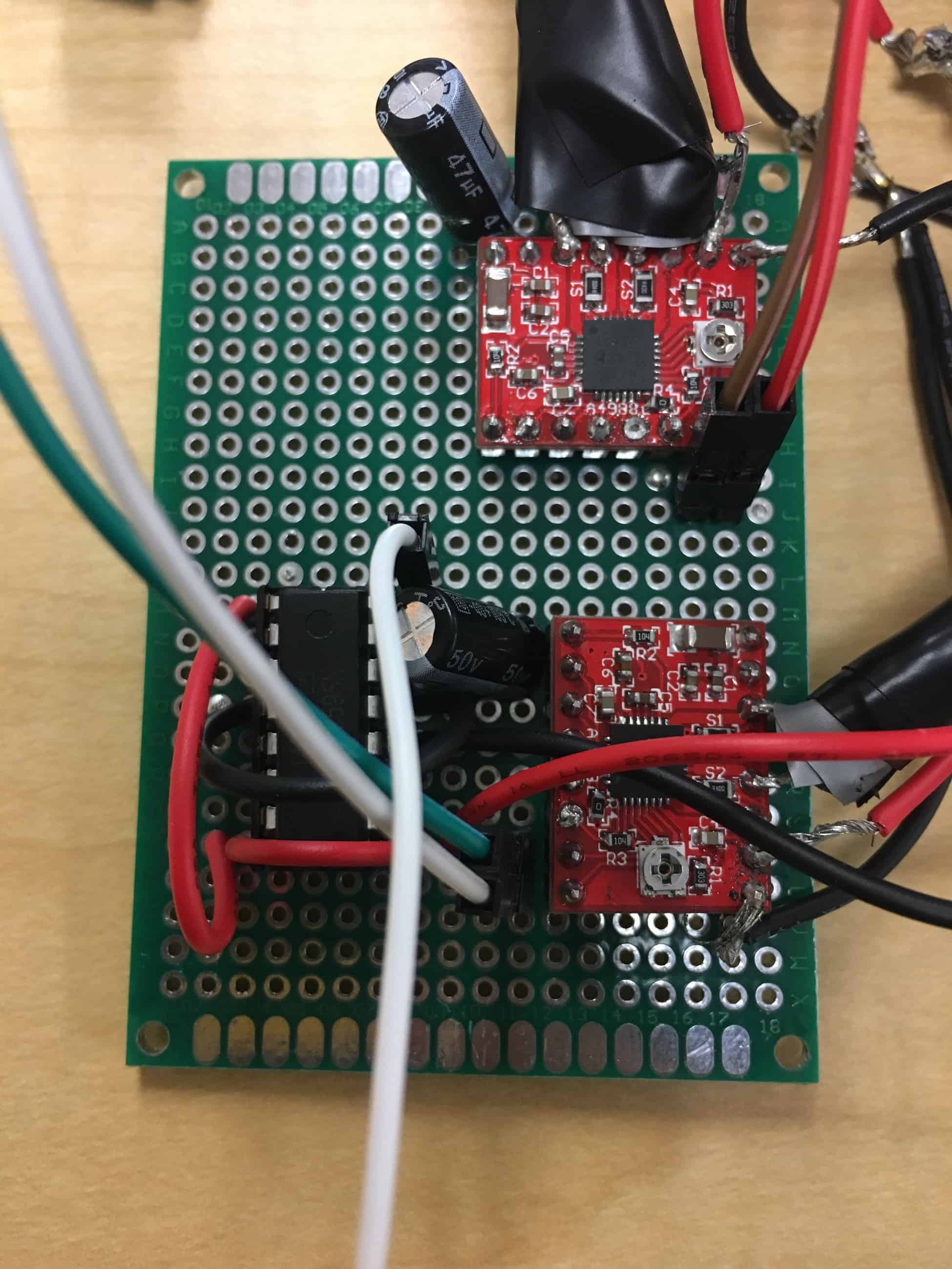
Later once the Y-axis motor started working again, the X-axis motor broke down. It broke during the very last week which tightened up my schedule. It was difficult to fix this one as the problem laid in the motor driver itself; however, I did not know that in the beginning. After many tests, I thought that the motor itself was broken so I switched out the motor. It was once I switched out the motor that I realized the motor driver was the problem, but I did not have a lot of time left. I had to try to rush through the code and connections to finish the project in time. With the help of instructors, I was able to finish everything. The code itself was relatively easy. Much of the arduino code was based on already existing code and I used an already existing gctrl program.  At the end, I was able to finish everything and successfully run my project at demo night. 


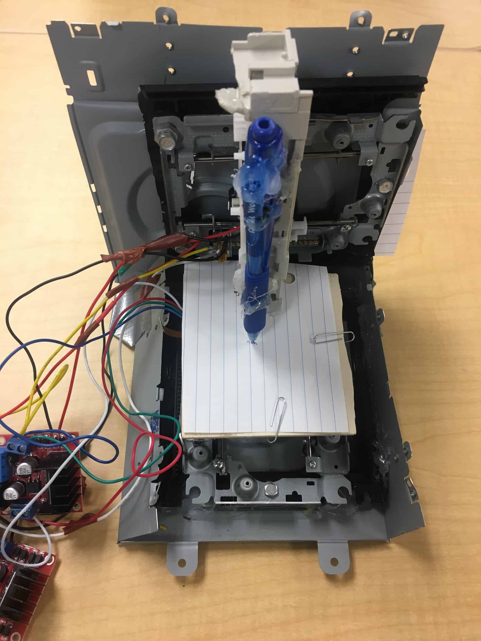
Modifications I have in mind for this project is to one, make it wireless and two, make it on one plane. This means that instead of installing motors perpendicular to each other, I’d instead have them on one plane so that only the pen moves instead of the pen and paper base. 


Overall, this project has taught me a lot about engineering as a whole. It taught me how to work on my own and only ask for help when really necessary. In the future, I hope to do more projects like this.

Second Milestone

For this second milestone I completed all the wiring for my project. First I had to connect the stepper motors to the motor driver. By connecting stepper motors to the motor drivers, I will be able to control the stepper motors with code uploaded to the arduino. Then I attached the stepper motor drivers to a PCB board to make everything look cleaner. After that, I attached capacitors to the motor drivers. The capacitors are used to energize winding phases to create a rotating magnetic field while the motor is running. 

After doing that, I reached the point where I had to attach the pen moving mechanics. Originally, I was going to use a servo motor to move the pen up and down but upon further inquiry, I realized I could use another motor already present in the DVD players I had disassembled earlier in the project. This DC motor was already set up to move a plastic base up and down once provided a power source. I wired it to a microcontroller to control it. The microcontroller was also attached onto the PCB board. 

Some challenges I faced throughout the project was figuring out how to wire everything but this was solved just by researching how specific parts needed to be wired to others. Another problem I faced is that I realized that I currently need 2 power sources to move my motors. One for the arduino and another for the motor drivers. Eventually, my goal is to cut it down to one.

First Milestone

For this first milestone, I completed the base of my project. I had to disassemble 2 DVD players to get the 4 wire micro stepper motors and the rails. Later, these will serve to move the pen around to draw. I attached the 2 motors and railings perpendicular to each other that way one can move left and right while the other can move forward and back. In order to attach them perpendicular to each other, I scraped together parts from the DVD player. I attached the railings to the DVD holder and mounted that onto the outer shell of the player. Most things were either connected by screws or by hot glue. In addition, I also created the platform that will eventually be connected to the x-axis platform, serving to act as a platform for the pen to draw on.

Throughout this first milestone, I faced a myriad of issues. Most of them came up when I finished disassembling the DVD players. Initially, I was going to mount the rails onto wood platforms but at the time, the wood had not shown up. Because of that, I decided to test the arduino and the motor driver with a stepper motor that an instructor provided. While testing, I realized that the motor driver I was using could only connect to one stepper motor. Because of that, I found that I needed to either use 2 of the motor drivers I was already using or use a different smaller motor driver. I decided to use a different one because it would require less wires. Another problem I faced was scraping parts to replace the wood platforms I was gonna use. Instead of attaching the railings onto the wood, I decided to use parts of the DVD player which proved challenging because most of the parts were not flat and already had holes. Because of that, this step took a lot longer than I had originally planned for.

During this entire process, I learned a broad range of things such as learning how to use a dremel and a drill. I also learned how to wire my Arduino to a motor driver, although I likely will not use the motor driver as I opted to use the other motor driver that is wired differently. In addition to that, I also learned how stepper motors work. My stepper motors specifically are 2 phase stepper motors which means that inside of it, there are 4 copper coils and 1 magnetic rod. When the current flows into the coils and charges them, the magnetic rod turns which is seen as the motor moving. By charging different coils in different patterns, the stepper motor is able to move in a large range of steps which provides accuracy.

For my starter project, I chose the mini POV 4. I picked the mini POV 4 because it provides opportunities to practice soldering and also allows me to learn the purpose of different components. The mini POV 4 turns on through a switch on the battery holder. Once on, the LED’s flicker to a pattern of a specific design that can be uploaded to the PCB board through the USB B-type jack. The mini POV 4 is powered by a 4.5V power source. It has 3 capacitors, 2 100 nano-Farad capacitors and 1 ceramic capacitor. The capacitors store electric charge to stabilize the voltage. There are also multiple resistors to help regulate the current. Each LED light has its own 47 ohm resistor to decrease the current in order to prevent the LED lights from burning out. There are also 3 2.2k ohm resistors to limit the current flowing to the transistor. The 3 transistors serve to amplify the current to the LED’s. This allows the microcontroller, which on its own does not have a strong enough signal to control LED’s, to control the LED’s. The microcontrollers purpose is to signal the LED’s to blink in a specific pattern. Finally, the variable potentiometer controls the input current that flows out. This allows for the circuit to regulate the speed of the LED lights blinking. Through this project, I learned how to solder and also learned the purpose for many electrical parts such as microcontrollers, transistors, capacitors, and many more. As I was making the mini POV 4, I faced many challenges. I had to desolder some parts because I soldered them in wrong in the first place or because I soldered wires too close to each other. In addition I had to research the purpose of all the parts because many of them were new to me.

STEM Summer Camps Coding & Robotics Classes For Kids San Francisco Coding & Robotics Classes For Kids New York Coding & Robotics Classes For Kids Denver Coding & Robotics Classes For Kids Palo Alto STEM Summer Camps For Kids in New York STEM Summer Camps For Kids in Palo Alto STEM Summer Camps For Kids San Francisco STEM Classes For Kids in New York STEM Classes For Kids in Palo Alto STEM Classes For Kids in San Francisco Code Classes For Kids Code Classes For Kids in New York Code Classes For Kids in Palo Alto Code Classes For Kids in San Francisco STEM Summer Camps For Kids

Leave a Comment

Start typing and press Enter to search

Bluestamp Engineering