
Introduction
My name is Casimir, and I am a rising senior at Dr. Michael M. Krop Senior High School. I successfully built a Light Organ which lights up an array of LEDs in response to sound and a touchscreen computer for my car which displays GPS data, plays music, and displays car diagnostics. I chose these projects mainly because of their practicality, as well as a necessity to expand my horizons in the field of engineering. I am fully familiarized with the field of mechanical engineering, so I therefore felt it was necessary to select projects that were more computer-oriented. The overall experience at bluestamp has been very educational, as well as enjoyable. Coming into the program, I had almost no knowledge of programming, coding, or electronics. However, through aiding other students, receiving advice from my instructors, and conducting independent research, I gained knowledge in all of the aforementioned fields. Moreover, I met a variety of people and gained connections I never would have had before. From the lecturers and instructors to other students, I gained valuable mentors and friends. Overall, my experience at bluestamp was a highly positive one. Unfortunately, as I graduate high school next year I will be unable to return as a student, but I definitely hope to return as an intern.
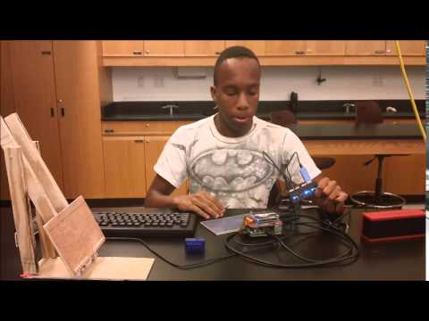
Main Project- Raspberry Pi touchscreen car computer


The touchscreen car computer is complete. It is powered by a Raspberry Pi, a small, compact computer. There are two operating systems contained on the Raspberry Pi, each downloaded, installed, and programmed via my computer onto an SD card, and each serving distinct and important purposes. The first, Raspbian, emulates Linux and Windows in that it appears as a normal desktop, with downloadable games and applications. The second, OpenELEC, functions as a media center, capable of playing video, music, and displaying pictures. Furthermore, I have added two modifications, the first of which being an application which will read car statistics via the OBD II connection present just under the steering column. A USB bluetooth adapter receives the information, and the application reads the statistics. Diagnostics displayed include speed, RPMs, and Intake. The second is a GPS functionality which displays numerical location data such as altitude, longitude, latitude, and speed. I also constructed a stand for holding the pi and screen for any time when I may need to make modifications or repairs outside of my car.
Final Video
Final Milestone
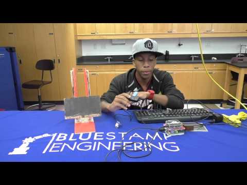
I have recently acquired the equipment necessary to read my car diagnostics, such equipment being a USB bluetooth adapter and an OBD II connector to the car, which also supports bluetooth functionality. Once I get home, I will be able to work on my car, and complete the programming and coding necessary to read the data coming from the OBD II connector. Moreover, I completed the programming for the GPS, having acquired a GPS breakout (which basically functions as an antenna) and a TTY adapter cable (which functions as a connection from the breakout to a USB port on the raspberry pi). However, the GPS functionality was not as I expected, as it only displays numerical data (such as altitude, latitude, longitude, speed, etc.) instead of the standard map and directional functions. I also crafted an additional layer to the original case, providing for the driver board for the screen, raspberry pi, and all the circuitry to exist in its own self-contained unit. The next step will be completed when I arrive home in Miami, and it is to simply install the screen, pi, and all necessary cables into my car. I am assured, however, that all systems will function correctly and effectively.https://youtu.be/8S2weKIaoaU


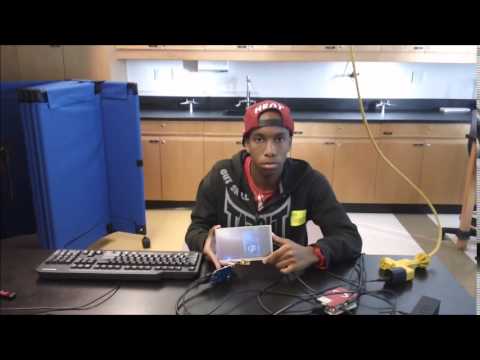
I was able to shift the orientation of the display on the 7″ LCD, enabling the touchscreen to work flawlessly. I have also installed a media center operating system onto the pi, allowing it to play music through the 3.5 mm audio jack. The pi automatically loads into a choice between loading to the normal operating system, Raspbian, or the media center, Openelec. So far, I have not been able to enable the touchscreen for Openelec, meaning I will have to use a small keyboard for playing music. The most challenging portion of the installation of the touchscreen was enabling a calibration program. However, it was later discovered that calibration was unnecessary, as all I needed to do was alter the display to fit the screen properly. In the future, I plan to add GPS capability through an adapter connected through USB.
Milestone #1

So far, I have activated my Raspberry Pi, and successfully connected it to the 7″ LCD screen. The Pi is powered by a mini USB connection, and connects to the LCD through HDMI. The LCD currently being used is powered by an AC/DC adapter, which converts the alternating current flowing from the outlet to DC power consumable by the LCD. However, I plan on acquiring a new LCD and touchscreen display, because a major problem was encountered in the calibration of the current touchscreen display. Initially, an image file called XBian was downloaded, installed, and mounted to the Pi via SD card. An image file for the Raspberry Pi is much like an OS for a normal computer. Much like users would not be able to perform actions, access the internet, or input commands on their computers without the use of operating systems such as Windows 8 or Linux, such actions cannot be performed on the Raspberry Pi without the presence of an image file. Thus, the image file XBian was loaded to the Pi, and the Pi connected to a power supply and the LCD. The next step was calibrating the touchscreen, which was carried out by way of an SSH connection to the Raspberry Pi. An SSH connection is one in which a normal computer is utilized to input commands into the Raspberry Pi by way of an internet connection to the same WiFi network. The necessary steps to calibrate the touchscreen were followed, involving inputting a variety of commands, but the touchscreen was not performing as expected. Left-Right motions were inverted, and touching the screen resulted in the mouse appearing a few inches above the correct position. I then performed multiple calibrations, both manually and automatically, only to come to the same result. I received this new touchscreen, and it functions surprisingly well. I am able to open desktop icons through touch, as well as select and move items. The next step is to edit the display by changing the screen orientation to landscape and calibrate the touchscreen. Moreover, I made a plexiglass case for my raspberry pi, and fitted it with Miami Heat logos for a personal touch.


I obtained this graphic from Raspberry Can, a blog providing schematics and tips for programming and using the raspberry pi.
Starter Project
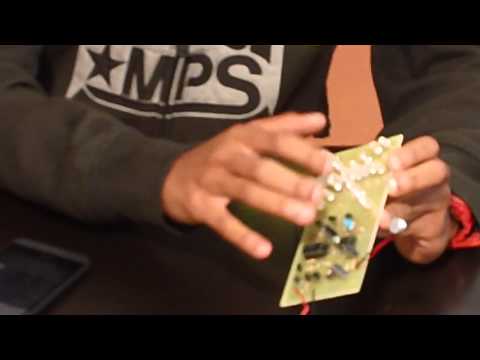
My starter project was the Light Organ, an array of LEDs which lights up in a pattern in response to sound, and is powered by a 9V battery. The circuit begins at the microphone, which employs magnets and electromagnetic induction to convert sound into an electric current. The current flows from the microphone to a series of three transistors, which work simultaneously to amplify the signal. The current is then sent to pin 3 on a microchip, which converts the current into a series of clock pulses (electric pulses that are sent rhythmically, like a metronome) that are sent outward through different pins on the microchip. A series of resistors are used to delay the signal coming from each pin, allowing the pulses to fall into a timed, steady “beat”. The pulses then flow into pin 14 on the microcontroller, which sends the signals outward to one of three transistors in sequence. Each transistor amplifies the signal again, and sends it directly to a set of six LEDs aligned in a star design around the central LED, which is powered directly by the microcontroller. In addition, there are two trimmer resistors present on the circuit. The first trimmer resistor adjusts the strength of the current coming directly from the microphone, thereby changing the sensitivity of the microphone. The second trimmer resistor alters the strength of the signal flowing into the first microchip, changing the pattern in which the LEDs light up. Finally, the electrolytic capacitors present on the circuit store energy. A problem encountered in the circuit’s construction was the lack of power flowing to the central LED. The problem was easily solved by adding more solder to the bare wire connecting the microcontroller to the central LED.
im so proud of my cousin you are very smart and very talented i love you so much and wish only the best for you in your joruney through life.