A Multi-Colored LED that can Simulate a Fireplace

My project is an animated flame that can simulate a fireplace by lighting up through a diffuser screen.

Engineer

Carson E

Area of Interest

Computer Science

School

Basis Independent Brooklyn

Grade

Incoming Sophomore

Reflections

While I was at Bluestamp I learned about many things, how to be independent and look things up on my own,  the basics of electrical and mechanical engineering, and so much more.  After this camp, I can continue to build engineering projects at my home and at other camps.  After Bluestamp, I will go into sophomore year at Basis independent Brooklyn where I can apply the engineering skills I got at Bluestamp to excel this year at school.

Final Milestone

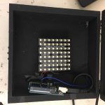
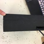
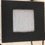
My final milestone is putting the LED matrix and the Arduino in the black box and coding the Arduino to tell the LED matrix to look like a flame.  The coding part was the easiest because of my previous programming experience in AP computer science. I knew how all the code worked and just had to understand what all the functions do. Then, I put the LED matrix and the Arduino in the Black box so light from the LED matrix would be blurry.   For the LED matrix there is a value for all of the individual LEDs and I used these to control all the LEDs in a specific custom pattern. I also changed the color the LEDs by running a loop so where the color changes with the number of times the code is run.  Overall this camp was very helpful for learning the different kinds of engineering and that just looking something up is normally the best way to solve a problem.

Code:  https://docs.google.com/document/d/1RHjiV87sZBOndN5lKm4kAJGrCkekQxgFFI0L2R9_ouo/edit?usp=sharing

Second Milestone

My Second Milestone is putting together and testing the Arduino Uno and the LED matrix.  The first thing that I did was look at how to connect the the LED matrix and the Arduino.  I found out that this is done by getting cables to connect the 5v, ground, and the Din connections. Din stands for digital input meaning that the LED matrix takes input from the Arduino and lights up the respective LEDs.  These connections are necessary to power the matrix, a ground for the circuit to reference, and input to go from the Arduino to the LED matrix. I had to connect these by soldering cables to the LED matrix. The soldering part was actually quite challenging because the area where I could hold the soldering iron was tiny and I almost burnt one of the LEDs.  Then I tested if it was working by loading up the Arduino IDE on my computer and opening up one of the example code files from the NeoPixel library. These are files that are given for free when you download the libraries that are necessary for the code to run. These files are necessary because they have the functions that are necessary to control the LED matrix. I learned how to load up example code from a library and how to install libraries.

First Milestone

My first milestone is constructing the housing for my LED matrix.  I painted my box black and cutting holes in it. This box is made of a lid and a base.  On the lid, I cut a square hole to make a diffuser screen. I cut this square hole by using a dremel.  A dremel is a device that spins a blade around very fast so that is cuts through stuff very easily. I cut this hole so that the light can escape the box. I made a diffuser screen so that the light is fuzzy as opposed to the detail of  individual pixels. On the side of the base, I cut a hole for wires to go in and out. This part was almost more challenging than working with the lid because the dremel head was larger than the hole I had to make so I ended up making a hole that was bigger than was necessary.  The whole process was challenging for this section because this was my first time using a dremel. Although this part was challenging it was very fun because the dremel is fun to use.  All of the pieces that I used are here.   Materials: https://docs.google.com/spreadsheets/d/1-Y2pQ-RDB8PwN1TPeIulr9WJGeiHgllENSGU1VPtdSs/edit?usp=sharing
[/vc_row_inner]
[/vc_column_inner]

Binary Blaster

For my starter project, I built a small game called a Binary Blaster.  The Binary Blaster is a game where a number from 1 to 15 is displayed on 2 7 seven segment displays then the user has to press buttons to make the binary number related to the decimal number displayed.  First I put on buttons these buttons send a boolean Value, a value that is either true or false,  to the next piece which is the IC chip. An IC chip the main computing ship of the blaster where all pieces are controlled.  This IC chip  takes a random value from an array List  and displays it to a 7 segment display. When a random number is chosen it gets deleted from the list so that the number is not chosen again.  Then it takes input from the buttons to see if the value on the displays and the value from the buttons are the same if they are then it shows a new number and if  it doesn’t it restarts the game.  Another piece is the piezo buzzer whenever there is input the IC chip tells the buzzer to make a noise.  It does this by making crystals vibrate.  Another piece is the switches,the first switch completes the loop with the batteries so that the Blaster turns on and the second switch completes the loop that activates the Piezo Buzzer.

Leave a Comment

Start typing and press Enter to search

Bluestamp Engineering