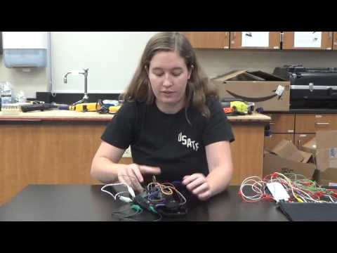
Hi! My name is Caitlin, and I’m a rising senior at Los Gatos High School. My starter project is the Binary Blaster, and my intensive project is a knee sleeve that measures the angle of the knee during physical activity, as well as the angular velocity of the knee.
REFLECTION
Wow, six weeks has sped by. I had absolutely no idea what to expect entering this program, but the amount of knowledge I have gained about myself as well as engineering thanks to BSE is unparalleled. I came here having never built anything before. I didn’t know how to go about designing a project, much less physically producing it. But as I walk out the door six weeks later, I have a working knee sleeve that does exactly what I want it to. I’ve learned how to code, how to problem solve, and to be confident in myself.
One of the biggest discoveries I had during BSE is that every problem can be solved. I won’t lie, I’m really into instant gratification. If I’m faced with a problem, and I can’t immediately solve it and feel proud of myself, I get frustrated. I faced problems every step of the way during this program, and none of them had exceptionally easy fixes. There were plenty of times where I stared at my computer screen and told myself “well, I guess I’ll just scrap this part of the project since there’s no way I’m figuring any of this out. If google can’t help me, nothing can.” But lo and behold, I would work and work and stare at my computer screen until my eyes lost focus and I’d eventually get a solution. I felt so much more pride figuring out a problem that required a lot of work rather than one that was merely a small hiccup that’s easy to fix.
This program has also given me more confidence and pride than anything else I’ve ever done. Obviously building something that works fills me with pride, but that’s what it’s like with every engineer. Engineers do what they do because building stuff is awesome and it gives you a rush of excitement when it works. I got that same rush of excitement and pride, but I also slowly found my confidence as the weeks went by. I was very insecure about the complexity of my project. Everyone around me was building these super cool robots and databases with tons of code, whereas mine was relatively simple with little code. This thought troubled me frequently during the first few weeks of camp. I want to pursue biomedical engineering in college, and I found that the main staple of biomedical engineering is simplicity. There is no point in designing an overly complicated device that befuddles the user. My knee sleeve is very simple, but it does exactly what it’s supposed to. It allows people to monitor their biomechanics without needing a physical therapist to tell them if they’re squatting and jumping correctly. Therefore, there’s nothing for me to be insecure about. I should be confident and proud of myself, since I designed an project that came right straight my mind, and I taught myself knowledge that will deeply benefit me in the long run.
So to make a long story short, these six weeks were awesome. I built a sweet knee sleeve that’s simple but exceptionally useful, I built up my knowledge in engineering subjects, and I built up my confidence.
FINAL PROJECT
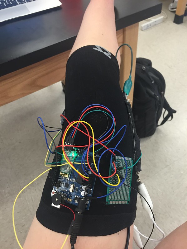
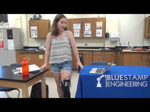
The finished product!
My intensive project for BlueStamp was a self designed knee sleeve that measures the angle and angular velocity of a person’s knee while that person is exercising. I came up with this idea because I tore my ACL a few years ago playing basketball and lacrosse. As I worked with a physical therapist I came to realize that it’s difficult to correctly do rehab exercises at home when there’s no one to tell you if you’re doing them right. This sleeve is designed to help people monitor and improve their biomechanics and they do certain exercises like jumping and squatting.
The knee sleeve can be broken down into two main parts. The first part is the bend sensor. This sensor measures the amount of resistance running through it, and then an algorithm translates this resistance into the angle of the knee. The angle isn’t all that accurate since the resistance is constantly changing, even with the smallest shift of gait. However, this sensor is hooked up to a buzzer that is set to go off if a person starts buckling his or her knee when jumping or landing from a jump. This buzzer will not go off until the person corrects the knee position, and places the knee back over the foot. Although the angle of the knee isn’t all that accurate, the buzzer is great at going off the second the knee starts to buckle, and it won’t stop until the knee is 100% in the right position.
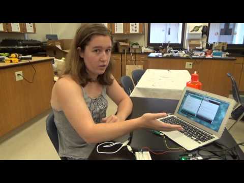
The second part of the sleeve is the accelerometer. It’s an MPU6050 that also has a gyroscope in it, and it has 6 degrees of freedom. To get a better explanation, feel free to see my third milestone where I go more into depth about the technical aspects of it. The accelerometer has two main functions: it measures the angle of the knee, and it measures the angular velocity. The accelerometer’s data can be displayed in Processing, where it shows all the measurements being obtained from the MPU6050. It’s possible to see the angle of the knee when someone squats, and you can see how it changes as a person goes through different exercises. The angular velocity can also be used to determine whether or not a person is doing cuts correctly. The angular velocity of someone’s knee should stay relatively constant as they do a cut, but if it decreases and increases again, it means that the person is cutting with the knee first, and then the hip is following, which is bad.
My biggest problem was the serial monitor. All throughout the project, I constantly had troubles setting up the serial monitor so that it would display data, connect to the Bluetooth module, connect to Processing, and so on and so forth. I was able to debug most of my code with only a bit of difficulty, however I would always become stuck when it looked like everything was correct, but nothing would show up on the serial monitor. This was especially true for the Bluetooth module. I didn’t set up input and output pins, so the Bluetooth didn’t know how or where to send the data that it was collecting. I also realized that once the Bluetooth had input and output pins on the Arduino, I needed to disconnect them every time I upload a sketch via USB, since you cannot upload a sketch over Bluetooth. The Arduino would freak out if the input and output pins were still connected as I uploaded something over USB because it didn’t know whether to use the USB cable or output pin to upload the sketch. After fixing this, it everything worked like a charm and I didn’t need any outlandishly large wires to connect my sleeve to my computer.
My next step is going to be creating a foot pressure sensor. It operates the same way as the bend sensor does, by measuring the resistance between two sheets of neoprene. This can be used to tell where a person rests the majority of their weight when it comes to their feet, which can be another telltale indicator of whether or not they have good biomechanics. For example, if they rest a majority of their weight on the inside of their feet, it means that they’re putting unnecessary amounts of stress on their knees. I’ve already begun a prototype model of the pressure pad, however it doesn’t work. I messed up the stitching with conductive thread, which is bad because it effectively short circuits the circuit I tried to set up. I also didn’t set up the Arduino pins correctly, which caused the data to be incorrectly transmitted, or transmitted not at all. There’s also a mess of wires which can definitely be cleaned up. I’ll definitely have my hands full as I continue to work on it, however the confidence I’ve gained from building the knee sleeve leads to me to believe I’ll definitely get the pressure pad working eventually.
THIRD MILESTONE
The third milestone of my project was getting my accelerometer and gyroscope to work. I worked with an MPU6050, which gives the user “6 degrees of freedom.” This means that it can measure movement going up, down, left, right, forwards and backwards. It also measures rotation in the X, Y and Z directions, also called yaw, pitch, and roll.
The nice thing about the MPU6050 is that it’s very easy to get data from, however it’s difficult to filter this data, and to make sense of the 6 values it outputs. I was lucky enough to find code online that filtered the data for me, and also put it into a nice looking graph in Processing. The code uses Kalman filtering, which is a lifesaver. This type of filtering essentially uses matrices to predict what the data outputs will be in the future, and then compares those outputs to the data in realtime. It then creates a “weighted average” that helps smooth out the data and make it more accurate. The only problem I had with the data was the yaw values. Yaw measures the direction that the device is pointing (like North, South, East and West but in degrees), which wasn’t helpful for my purposes. However, since there’s no magnetometer in the MPU6050, the devices loses track of where it’s pointing, which results in ridiculously high levels of drift. The bright side is that the code resets the yaw after it drifts too much, and that yaw serves no purpose in the measurements I’d like to obtain. The only issue I had setting everything up was that the serial monitor was difficult to set up since it was coded oddly, I had to seek out a library that I didn’t know I needed, and that there were a few lines that required debugging due to a forgotten semicolon or bracket. Those were easy fixes, but I still wasn’t done yet.
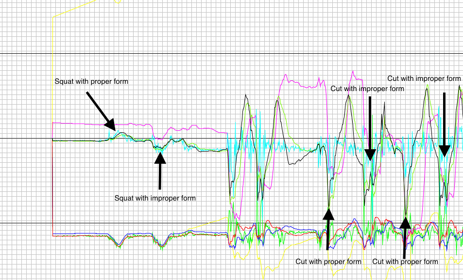
Now, the fun part of this milestone was figuring out how the graph of the MPU6050 data would help people either rehabbing or exercising. The first epiphany I had was that the graph would tell people when their knee was buckling inwards, and how much. Although the grid of the graph isn’t labelled, the solid black line above the x-axis represents 90 degrees. The user can eyeball a divot in the black line, which indicates the incline of the accelerometer from vertical, and guesstimate how much their knee has buckled. When a person squats, the black line should curve upwards and then downwards, creating a small hill in the graph. This represents the person’s knee going outwards when they squat, which is desired. If the person squats and creates a small trough in the graph, that means their knee is buckling inwards, and that they’re causing unnecessary stress on the joint. This feature mimics what the bend sensor does, however it’s more accurate (if a person cared to know exactly how much their knee buckled in), and it helps people who like visual realtime data of what their knee is doing. I was considering trying to label the grid so that people would know exactly how much their knee is buckling in, but then I realized that that knowledge is unnecessary. When squatting, the knee should never buckle inwards, regardless of what the angle is. Physical therapists don’t tell their patients to let their knees bend inwards up to 30 degrees or something like that, they just tell them to not have them buckle whatsoever. With this idea in mind, I decided to save myself a few hours of coding and not label the gridlines in Processing.
Another use of the MPU6050 data is determining if someone is cutting right. To lessen the torque on the knee during cuts, a person has his or her foot land, and then rotates both the hip and knee at the same time. Most people who have suffered knee injuries make the mistake of rotating their knee in the direction they’d like to cut before they rotate their hips too. This results in a lot of strain on the ACL and menisci, and is why a lot of people damage their knees doing cuts during highly agile activities like soccer, football and basketball. What I found with the MPU6050 data was that when the user cuts properly, there’s a divot in the graph, but it goes back to the x-axis in an almost smooth line. When they cut improperly, there’s a divot that usually has another small divot in it as the person swings his or her hips back around. This odd looking shape in the graph is because the knee picks up angular velocity as it swings into its new position, but then is forced to slow down/stop as the hips try to swing into position as well. This results in the top part of the leg rotating, but the bottom part staying static. With weak or damaged ligaments, or weak muscles, this can result in a tear of certain ligaments, or a knee sprain. It’s impossible to diagnose this without someone else watching you do cuts, so my knee sleeve can help people spot this nasty habit and fix it before it results in an injury, or it can help them fix it after they’ve already been injured.
Those explanations were a bit long winded and hard to imagine, so below you can find a graph of the MPU6050 data showing the two uses of the data as explained above. Also, if you look close enough, you can see a yellow line that goes way offscreen initially, and that’s the yaw.
SECOND MILESTONE
My second milestone of my intensive project was to get my bluetooth module hooked up and working with the Arduino and my computer, sew everything into the knee sleeve, and get my buzzer working in conjunction with the bend sensor. These steps sound much easier than they actually were.
I was very excited to start my work with the bluetooth module, a HC-05. I wanted to use bluetooth to transmit my data, since I figured that wearing a knee sleeve with a big USB cable hanging from it would be annoying, and it would hinder the types of exercise someone could do. I ran into my first problem with the module immediately. I would try to connect it to my computer, but it refused to connect. I scoured through forums for a solid two days, with no luck. Finally, I attempted to use the tried and tested method of turning my computer off and on again, and it worked! Things were looking up from there, or so I thought. I then ran into the problem of actually getting the bluetooth module to transmit the data I needed. Once again, I was stuck looking through mass amounts of forums and trying to figure out what half the people were talking about. However, I eventually came to the realization that I needed to create a new TX pin and RX pin. Basically, the Arduino didn’t know where to receive or transmit data from, since it usually transmitted data through a USB cable. With this information in mind, I just defined my new TX and RX pins as digital pins 0 and 1. Now, however, I couldn’t upload any new sketches to the Arduino if I had it plugged into my computer. I once again realized that to upload anything, I need to unplug the TX/RX pins, because if I don’t, my computer doesn’t know where to send the sketch to. After figuring this all out, my bluetooth module works like a charm, and I can officially say I have gone wireless.
My next step was to sew everything into my knee brace. Like with most parts of this project, this sounds far easier said than done. My knee sleeve is extremely small when not on someone’s leg, which means that trying to sew anything into it in that state would result in the thread just tearing. So, I was forced to slide the sleeve over a piece of cardboard, and then sew everything onto the sleeve. It was a tedious process, but it worked and now nothing will be falling off my sleeve anytime soon.
Finally, I programmed my buzzer to go off when the knee exceeds a certain angle. Since the angle is dependent upon the amount of resistance in the bend sensor, it’s not all that accurate. What I have come to realize though is that the buzzer will still go off when the knee buckles, and turn off when the knee shifts itself outwards into a mechanically correct position where the knee is over the toes. I am planning on looking into making the bend sensor a bit more accurate, but as long as the buzzer goes off when the knee buckles, it’s doing its job. Now it’s onto the accelerometer and gyroscope!
FIRST MILESTONE
My first milestone of my intensive project was to create my bend sensor, as well as to compile the code that would allow me to get data from the sensor. This data includes the resistance going through the sensor, as well as the angle of the sensor.
To make the sensor, I cut out two pieces of neoprene, and sewed conductive thread into them. I then sewed conductive fabric onto the end of them, and ran the conductive thread through said fabric. I put one small sheet of velostat in between the two, since velostat is a pressure sensitive conductive fabric that would allow resistance to build up within the sensor.
I found some code online that would translate the resistance in the sensor into the number of degrees that the sensor was bent. This worked pretty well, but the resistance would jump around like crazy if I even just lightly bumped the table. To combat this, I created a smoothing algorithm that took the average of the values, which helped immensely by limiting the amount that the data jumped around.
After that, I decided that I would like my data to be graphically shown. With the way the data was outputted from smoothing algorithm, it was very difficult to get Processing (the graphing application) to read the data from the serial monitor. Therefore, I got another Arduino program that simply outputted the amount of resistance in the sensor. Then, I got a program in Processing that graphically displayed said amount of resistance. Although it has no units, it can show the user how exactly the knee is moving. An decrease in resistance means that the knee is buckling inwards, which isn’t desired. Below, you can find a screenshot of the graph as the sensor gets bent and unbent repeatedly. My next step will be to program a buzzer to buzz when the bend sensor exceeds a certain angle, and start stitching the bend sensor and Arduino into the knee sleeve.

BINARY BLASTER STARTER PROJECT
 The Binary Blaster starter project is a game where the user is presented a number, and then has to press the four buttons in a certain way to give the binary counterpart of that number. The game can also be played going from decimal to hexadecimal, if desired. The game goes up to 15, and if the player gets all 15 right, he or she wins. This project was essentially a crash course in soldering and following instructions. All of the components had to be soldered into the board, and the legs of the components were pretty close, which required very accurate soldering. The game works by having two AA batteries feed power into the circuit. There’s a 10 kilo-ohm resistor that limits the current flowing through the board. There are also two .1 microfarad capacitors that aid the seven segment displays in turning on quickly. There’s a buzzer and two switches that turn the device on and off, and that turn the sound on and off. The microcontroller randomizes the numbers given to the user to ensure that the user is actually learning binary, and that he or she isn’t relying solely on muscle memory. If desired, the user can hook the microcontroller up to an Arduino and re-program the game to change the rules. Once I finished the project, it refused to turn on. However, upon closer inspection, it turns out that one of the battery clips wasn’t fully in contact with the battery. After a bit of brute force, it touched the battery, the circuit was complete, and the game could be played.