R/C Hovercraft

A hovercraft that uses 55 mm fans to hover and move around.  It is controlled by a standard R/C controller.

Engineer

Bryant M

Area of Interest

Computer Science

School

Los Gatos High School

Grade

Incoming Senior

Demo Night

Reflection

Complete Model Hovercraft
My time at BlueStamp has been a great experience, and has opened my eyes to some of the aspects of engineering I previously knew little about, including mechanical and electrical engineering. My focus on these areas of engineering has taught me a lot about the designing and manufacturing processes, such as how mechanical engineers design parts and whole projects in CAD (Computer Aided Design) and how assembly often does not quite go as planned, and also how to make safe and solid electrical connections. Before this experience, I mainly knew aspects of and worked on projects in software engineering, but now I will be focusing on projects that include some sort of mechanical or electrical engineering.  These projects include a top for the hovercraft and small mechanisms that can make normal things easier. The independence I have had working on this project at BlueStamp has given me confidence in my work and has resulted in me learning a lot from my time at BlueStamp.

Here is the link to the original version that I looked at for reference.  My main dimensions are 21.33 cm wide and 42.66 cm long.

Final Milestone

Complete Hovercraft back view
Wire connections
Hovercraft lift fan and wire connections
Almost complete hovercraft
My third and final milestone was to install the electronics into the hovercraft. The major places I put the electronics were the small room just in front of the fan room and the custom-made spots for the motors. The lift fan fits into the bottom of the hovercraft, and does not need glue as it fits snugly and pushes itself upward. Some of the cords pass through holes in the walls that keep the cords somewhat in place while the craft is running. The thrust fan is attached to the servo in back to allow it to turn.

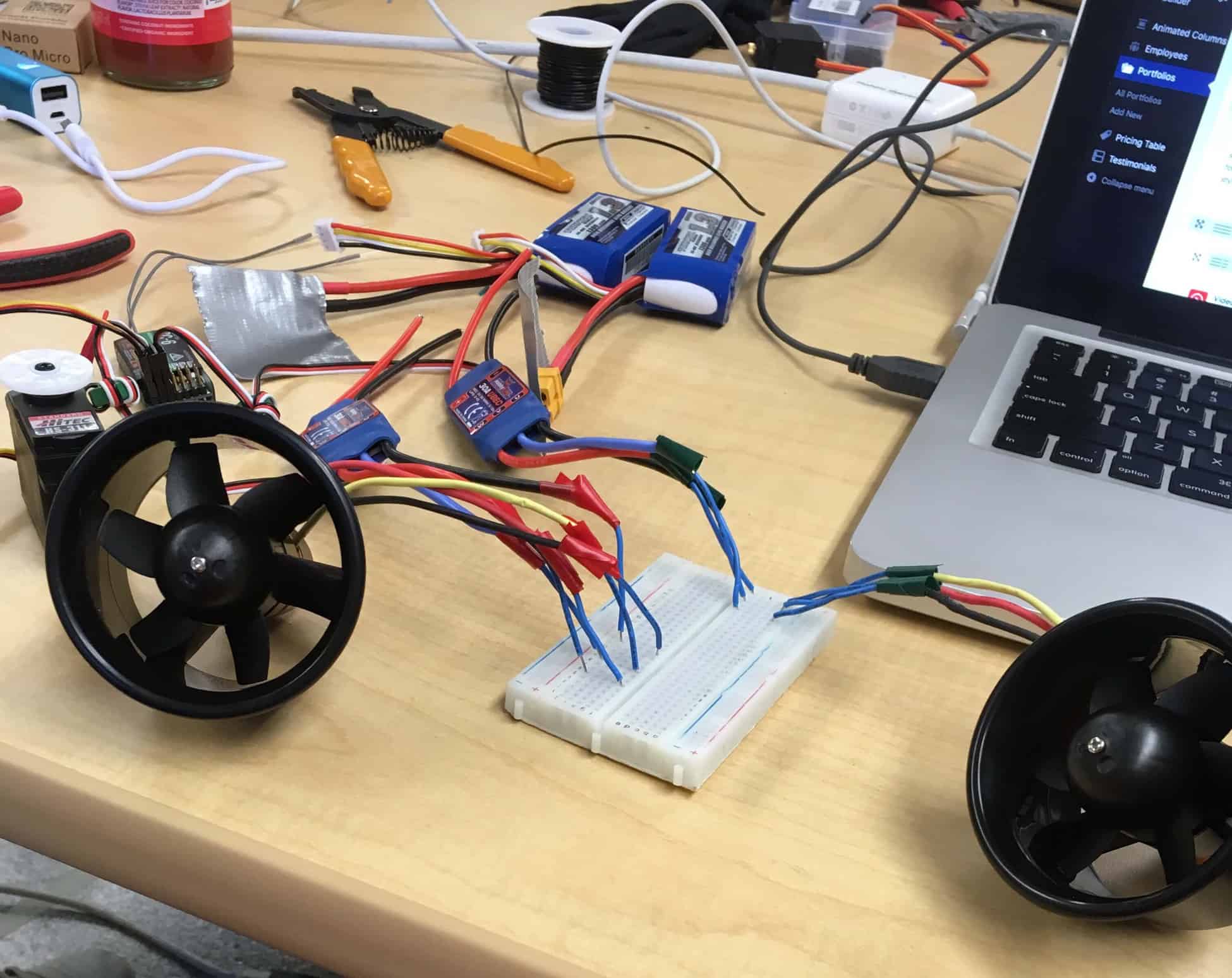
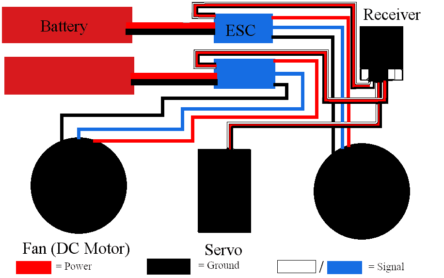
The first challenge was that I had to make the connections more permanent so that they would stay connected on their own. For the fan-ESC connections, I just soldered on banana plugs and covered them in heat shrink to provide easily disconnectable connections. The battery-ESC connections were tougher because the batteries have special connectors attached to them called XT60 connectors and the ESCs do not. I overcame this by buying some connectors of the same type and soldering them on to the ESC wires. I also covered these in heat shrink. Another major challenge was weight distribution. If one side of the hovercraft is heavier than another, the hovercraft will drift off without any inputs being pressed. To overcome this I made the batteries and most of the rest of the electronics symmetrical because the batteries are the heaviest parts. The last major challenge with this milestone was attaching the thrust fan to the servo in the back. It needed to be secure and also balanced, so I decided to use hot glue to attach it. Here are my bill of materials, build plan, and PDF version of the STL file. The STL file can be downloaded below.

Second Milestone

hover craft base in progress
Hovercraft Fan test fit
In progress Hovercraft skirt
Hovercraft base isometric
Hovercraft top no roof
Hovercraft no roof side view
Hovercraft base sketch
Hovercraft isometric no roof
My second milestone was to build the hovercraft itself. The hovercraft is made of depron foam, and has a 5 layer base, which allows the fan to fit inside comfortably. One of these is mostly empty to reduce weight and increase air flow inside the skirt area. The layers also have different sizes, allowing the skirt to be attached more easily. The skirt is made of nylon tent fabric, and is super glued onto the base of the hovercraft. There are also thin strips of tent fabric on the underside of the skirt helping it keep its curved shape. When the fan is running, the skirt should puff out and keep plenty of air underneath the hovercraft. The top part of the hovercraft is a housing for the electronics, and consists of several walls of foam super glued to the top of the base. There is a hole in the base and a small housing in the back of the craft to hold the motors in the finished product.
One challenge I faced while completing this milestone was that I had to design and cut out the parts myself. I had a rough guide from prior projects, but exact measurements and ratios were tough to get. To assist in the designing of the parts, I learned to use a CAD program. This allowed me to relatively quickly design the necessary parts. I also had to pick an order to assemble the parts in as there are many connections that I had to make sure were positioned properly. By planning out a few glueing operations ahead, I was able to glue all of the parts together without issue. The last major challenge I faced was curving the skirt. Because it must be curved around the base of the hovercraft, it is difficult to keep that shape as it turns around corners. By splitting the skirt into two parts and connecting them again later, this task became much easier.

First Milestone

My first milestone was to assemble the electronics independently of the hovercraft itself. I have two fans, one of which lifts the hovercraft of of the ground and the other of which pushes the hovercraft around. Each of these needs an electronic speed controller (ESC), which takes power from the batteries and receives control signals from the receiver. The ESC runs the signals from the receiver through its firmware to determine how fast the motor should run. It also contains a battery eliminator circuit that provides power to the receiver. The servo rotates to a set position based on the input it receives. In the hovercraft it rotates the thrust fan to allow the hovercraft to turn, and connects to the receiver directly.  The receiver needs to get power from one, but not both, of the ESCs and it receives signals from the transmitter. The transmitter emits radio waves holding the signals from the sticks, and the receivers turn those waves back into electrical signals.
One challenge I faced while completing this milestone was that the receiver can only get power from one ESC, but both need to plug into it. Rather than cutting it, I removed the middle connector from one of the ESC plugs and covered it in electrical tape to prevent shorts and still keep open the option of putting it back in if necessary. I also had to figure out how to connect the ESCs to the batteries and fans in secure enough ways to hold a connection. I overcame this by using duct tape to hold the ESC wires connected to the battery, and soldering small wires to the fan and ESC wires that needed to connect, and then putting those in a breadboard. These somewhat temporary connections allow it to work when connected to the transmitter.

Starter Project

My project was the Useless Machine. When the switch is flipped, it brings an arm out of the box and turns itself off.In this project, the frame and arm are made out of acrylic, and there are various electrical parts. The switch sends a signal of which direction the arm should go based on its position. The snap switch stops the circuit from moving back while pressed. The resistors make sure the amount of current is appropriate for the LED and motor by converting extra electrical energy into heat energy. The screw terminals provide an electrically conductive connection between the circuit board and the wires that go to the batteries and motor. The LED only allows electrical current to run in a single direction, and when current is run through it, it emits light.
There were a few challenges in this project. One was soldering parts with legs that can’t be bent (switch, screw terminals, snap switch). I overcame this by using tape to hold the parts in place on the PCB while I soldered one leg. I then removed the tape and used the soldered leg to hold the part in place. Another challenge was getting the top to fit on the sides. The instructions didn’t mention to remove the nuts and washers on the switch, but that is what you’re supposed to do. I had to check the pictures in the instructions to figure out what it was supposed to look like before and after putting on the top. The sides also kept falling in, which took a little fiddling to make them stay up. I slotted them into the top one by one rather than trying to get them to fit all at once. Overall, I got the project to work as intended, using a small circuit with multiple switches to turn itself off.
Useless Machine

Leave a Comment

Start typing and press Enter to search

Bluestamp Engineering