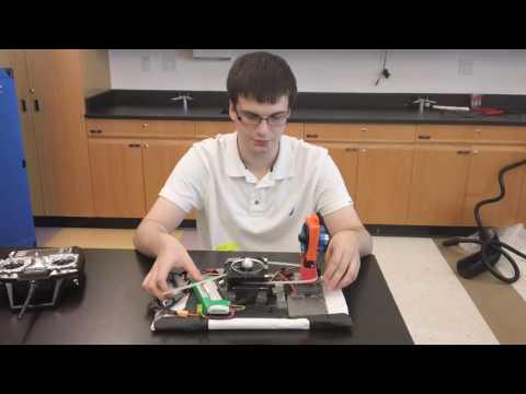
Hi! My name is Brent, and I am a rising senior at Northern Valley Old Tappan Public High School. I have been involved with different forms of engineering throughout my high school and middle school education. I have participated and continue to participate in team-based engineering competitions. For my main project, I worked on an R/C hovercraft.

BlueStamp has been one of the most beneficial engineering experiences I have ever had the pleasure to take part in. I spent more time hands on with electronics than I have ever had the chance in high school, and I learned how to use a variety of tools and how to design and contstruct electrical circuits. Most of all, BlueStamp taught me perseverance. During the construction process, many of my original parts did not work correctly; I had to improvise solutions and make critical decisions about what I could fit into the project and what had to be cut due to time constraints. I learned the value of relying on my own ingenuity to solve problems, and I was able to become a more successful person and engineer because it. While there were many difficult points along the way, I was able to gain valuable skills that I can use both in engineering and in life.
Final Project Description:
The hovercraft, which I have named the Levkov for the famous Russian inventor of the 1930s who experimented with some of the first hovercraft technologies, is composed of a three layer Depron foam frame. This frame supports a rectangular prism that holds the 64mm lift fan in place and directs thrust downwards into the air vents in the second layer. The rectangular prism is made of several pieces of Depron and laser cut pieces of wood stacked on top of each other.
The thrust fan is secured in a mount that allows it to be bolted on to the servo motor’s horn. This allows it to be removed if it receives damage from a circumstance such as foreign object entry. The servo motor and lift fan are together a thrust vectoring system that allows the hovercraft a wide degree of very precise motions.
The lift effect is created by the lift fan directing air into the second layer of the hovercraft. This second layer is mostly composed of air with only a few pieces of Depron that forwards the air to the major sections of the skirt. The skirt is made of outdoor tarp material that is heavy duty. The tarp skirt has a large hole cut into the bottom to allow the air to escape and cause the hovercraft to float on a surface.

 This is the model for the thrust fan mount. Note the bracket on the bottom which allows the piece to be screwed into the servo horn  This is the SketchUp model for the final chassis. Note the three layers that comprise the main structure of the hovercraft. |
Below are ZIP files for the CAD models used for the hovercraft’s design along with the Bill of Materials for the project.
recessed motor mount for directional edf version 6
First Milestone
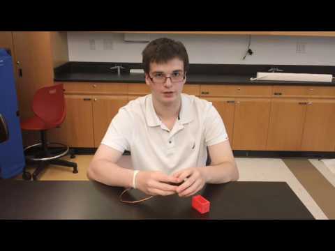
For my first milestone, I developed a 3D-printed servo mount and learned about the mechanics behind hobby servo motors.
This servo mount allows the servo motor, which was chosen because its motion can be precisely controlled, to be securely fastened onto the hovercraft without having to actually permanently attach the servo motor. This means that the servo motor can be replaced fairly easily and quickly if it is damaged and must be removed.

Starter Project
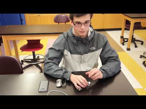
For my starter project I created the MintyBoost. The MintyBoost is a portable phone charger that converts the three volt energy of two AA batteries and converts it into the five volts necessary to charge USB capable devices such as smartphones and music players.
The MintyBoost utilizes an inductor to convert electrical energy into magnetic energy that is then used to induce a current into the LT1302 integrated circuit; the IC then switches “on” via its transistors and tells the inductor to supply more energy. Electrons are then forced through the inductor, “stepping up” the voltage from 3 to 5 volts. The energy is then forwarded to capacitors connected to the USB port; these capacitors regulate the energy and prevent the outgoing voltage from fluctuating in a way that would damage the charging device.
I faced several challenges in this project. One such challenge was the rapid temperature rise in the case, the board and the batteries. This was because the bottom of the circuit board contained metal pieces that touched the metal surface 0f the can. The can acted as a conductive surface that resulted in very noticeable heat increases in the device. The issue was solved by applying electrical tape to the area where the circuit sat in the can; the electrical tape acted as an insulator that prevented contact between the two conductive metal surfaces. I also had to replace a resistor that was missing from the kit; this task was accomplished by matching the color bands on the resistor that the project did have to those of a new resistor. The last challenge I had to face was reattaching a wire to the circuit that had broken off, and it took some work to reopen the terminal to allow the soldering of a new wire.