Arduino Pong Game
Engineer
Benjamin R
Area of Interest
Mechanical Engineering
School
Winston Prep
Grade
Incoming Sophomore
Reflection
As a returning student from last year, my goal was to make this year an improvement from my time at Bluestamp in 2018. Before long, I noticed how much better I was compared to last year. I was more independent and I was more creative in finding ways to work around problems I encountered. In my opinion my favorite moment of the program was the first half of the third week. I was excited to keep moving forward and I had a lot of ideas on how to build the box. Overall, I liked this year of Bluestamp a lot and I hope I can improve even more next year.
Final Milestone
I finished my project! I wired a second LED, download edthe pong code, and added sound.
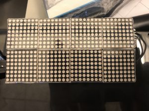
I began wiring the second LED matrix. I thought I would just wire it the exact same way I wired the first one.
In reality, I had to connect both LEDs by soldering wires that connected the input of one matrix and the output of the other.
The wiring was a prevalent issue but I pushed through.
After getting the pong game to consistently work, I went on to adding the sound.
SInce I did not know how to wire a buzzer, I practiced on a separate breadboard before adding it to the pong setup.
At this point, I was eager to start building the box, but before I could start, the code stopped working.
I had an issue where my Arduino stopped working due to consistently pulling so much energy for the LED matrices.
After switching Arduinos, I could finally move onto putting the project into a box.
This part was mostly straightforward, but the disorganized wiring became a problem once again.
There were multiple times when a wire disconnected and I had to search around and find it.
I decided to make two holes for the potentiometers to fit in, and to have the LED attached to the top of the box.
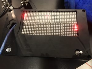
Later, I decided to fit the LED inside the box so it didn’t stick out.
I cut the hole with a jigsaw and filed the box a lot to get it to fit.
Eventually I cut the holes into a piece of teflon and that helped everything stick.
Overall, this project taught me a lot.
I struggled a lot near the end, but that just taught me to be more organized in the future.
Overcoming these challenges made me more experienced in dealing with them in the future.
Figure 2: Project in a box without lid
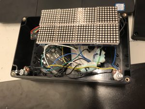
Figure 3: Finished Pong game
//Source: https://github.com/mmaccoby1/arduino_pong/blob/master/code.ino
//We always have to include the library
#include "LedControl.h"
byte rightscore = 0;
byte leftscore = 0 ;

byte pongdisplay[] = {     // Used upon start up to display "Pong"

  B00000100,
  B00000100,
  B00000100,
  B00000100,
  B01111100,
  B01000100,
  B01000100,
  B01111100,
  B01111100,
  B01000100,
  B01000100,
  B01000100,
  B01111100,
  B00000000,
  B00000000,
  B00000000,
  B01000100,
  B01000100,
  B01000100,
  B01000100,
  B01111100,
  B00000000,
  B00000000,
  B00000000,
  B01111100,
  B01000000,
  B01000000,
  B01111100,
  B01000100,
  B01000100,
  B01111100,
  B00000000,
};

byte zero[] = {    // Used to display a '0' for when displaying the score
  B00000000,
  B00011100,
  B00100010,
  B00100010,
  B00100010,
  B00100010,
  B00011100,
  B00000000
};
byte one[] = {     // Used to display a '1' for when displaying the score
  B00111110,
  B00001000,
  B00001000,
  B00001000,
  B00001010,
  B00001100,
  B00001000,
  B00000000
};

byte two[] = {      // Used to display a '2' for when displaying the score
  B00000000,
  B00111110,
  B00000010,
  B00001100,
  B00010000,
  B00100000,
  B00100010,
  B00011100
};
byte three[] = {    // Used to display a '3' for when displaying the score
  B00000000,
  B00001100,
  B00010010,
  B00010000,
  B00001000,
  B00010010,
  B00010010,
  B00001100
};

byte four[] = {      // Used to diplay a '4' for when displaying the score
  B00100000,
  B00100000,
  B00100000,
  B00100000,
  B00111100,
  B00100100,
  B00100100,
  B00100100
};
byte five[] = {      // Used to display a '5' for when displaying the score
  B00111100,
  B00100000,
  B00100000,
  B00111100,
  B00000100,
  B00000100,
  B00111100,
  B00000000
};


byte matrix = 0;      //variables to help display paddles, scores, and "pong"
byte displayrow = 0;
byte displayindex = 0;

/*
  Now we need a LedControl to work with.
  pin 12 is connected to the DataIn
  pin 11 is connected to the CLK
  pin 10 is connected to LOAD
  there are 8 matrices to control
*/

int row;                                    //these variables store the location of the ball
int col;
byte deflect;                               //used if the ball must bounce off a wall

LedControl lc = LedControl(12, 11, 10, 8);  //initializes LED controller

byte dirx;                                  //these variables store the direction the ball is moving
byte diry;
byte start;                                 //used to start a new game after a player scores

#define leftpaddle 0  //left pong knob is connected to analog input 0
#define rightpaddle 1 // right pong knob is connected to analog intput 1
int rightpongval;     //holds the position of the right paddle
int leftpongval;      //holds the position of the left paddle

byte pong[] = {          // Stores the position of the ball and paddles, initially set as blank
  B00000000, B00000000,
  B00000000, B00000000,
  B00000000, B00000000,
  B00000000, B00000000,

  B00000000, B00000000,
  B00000000, B00000000,
  B00000000, B00000000,
  B00000000, B00000000,

  B00000000, B00000000,
  B00000000, B00000000,
  B00000000, B00000000,
  B00000000, B00000000,

  B00000000, B00000000,
  B00000000, B00000000,
  B00000000, B00000000,
  B00000000, B00000000,

  B00000000, B00000000,
  B00000000, B00000000,
  B00000000, B00000000,
  B00000000, B00000000,

  B00000000, B00000000,
  B00000000, B00000000,
  B00000000, B00000000,
  B00000000, B00000000,

  B00000000, B00000000,
  B00000000, B00000000,
  B00000000, B00000000,
  B00000000, B00000000,

  B00000000, B00000000,
  B00000000, B00000000,
  B00000000, B00000000,
  B00000000, B00000000
};


void setup() {
  pinMode(leftpaddle, INPUT);   //the paddle is an input.
  pinMode(rightpaddle, INPUT);  // the paddle is an input.

  Serial.begin(9600);  // serial communication for debugging. Set to 9600 baud

  // These statements below go through and set up the matrices to the given settings
  lc.shutdown(0, false);
  lc.setIntensity(0, 15);
  lc.clearDisplay(0);

  lc.shutdown(1, false);
  lc.setIntensity(1, 15);
  lc.clearDisplay(1);

  lc.shutdown(2, false);
  lc.setIntensity(2, 15);
  lc.clearDisplay(2);

  lc.shutdown(3, false);
  lc.setIntensity(3, 15);
  lc.clearDisplay(3);

  lc.shutdown(4, false);
  lc.setIntensity(4, 15);
  lc.clearDisplay(4);

  lc.shutdown(5, false);
  lc.setIntensity(5, 15);
  lc.clearDisplay(5);

  lc.shutdown(6, false);
  lc.setIntensity(6, 15);
  lc.clearDisplay(6);

  lc.shutdown(7, false);
  lc.setIntensity(7, 15);
  lc.clearDisplay(7);

  //display the initial "pong" text
  while (matrix < 4) {
    while (displayrow <= 7) {
      lc.setRow(matrix, displayrow, pongdisplay[displayindex]);
      displayrow++;
      displayindex++;
    }
    displayrow = 0;
    matrix++;
  }

  delay(1000);
  displayscreen();
  start = 1;
}

void loop() {

  paddles();
  pongsim();
  displayscreen();
}


void paddles() { //reads data from the paddles and displays that in the array

  // reads in the values from the potentiometers used to control the paddles
  // converts the values to an integer from 0-13 corresponding to the row of the bottom bit of the paddle
  leftpongval = analogRead(leftpaddle);
  leftpongval = map(leftpongval, 0, 1010, 0, 13);
  rightpongval = analogRead(rightpaddle);
  rightpongval = map(rightpongval, 1020, 20, 0, 13);

  //clears the previous paddle inorder to display the next one
  for (int x = 0; x < 2; x++) {
    for (int i = 0; i < 8; i++) {
      bitClear(pong[i + 32 * x], 0);
      bitClear(pong[24 + i + 32 * x], 7);
    }
  }

  //-------------------------------right paddle

  if (rightpongval < 6) {                      //display the paddle on the lower matrix
    bitSet(pong[rightpongval + 24], 7);
    bitSet(pong[rightpongval + 25], 7);
    bitSet(pong[rightpongval + 26], 7);
  }

  else if (rightpongval > 7) {                       // display the paddle on the upper matrix
    bitSet(pong[47 - rightpongval], 0);
    bitSet(pong[47 - rightpongval - 2], 0);
    bitSet(pong[47 - rightpongval - 1], 0);
  }

  else if (rightpongval == 6) {                      // cases for displaying the paddle across both matrices
    bitSet(pong[30], 7);
    bitSet(pong[31], 7);
    bitSet(pong[39], 0);
  }

  else if (rightpongval == 7) {
    bitSet(pong[31], 7);
    bitSet(pong[39], 0);
    bitSet(pong[38], 0);
  }


  //----------------------------------left paddle
  //due to the configuration of the cascading displays, there is a small amount of lag when moving the left paddle across matrices

  if (leftpongval < 6) {                                // display the paddle on the lower matrix
    bitSet(pong[leftpongval], 0);
    bitSet(pong[leftpongval + 1], 0);
    bitSet(pong[leftpongval + 2], 0);
  }

  else if (leftpongval > 7) {                               // display the paddle on the upper matrix
    bitSet(pong[71 - leftpongval], 7);
    bitSet(pong[71 - leftpongval - 2], 7);
    bitSet(pong[71 - leftpongval - 1], 7);
  }

  else if (leftpongval == 6) {                             // display the paddle across matrices
    bitSet(pong[6], 0);
    bitSet(pong[7], 0);
    bitSet(pong[63], 7);
  }

  else if (leftpongval == 7) {
    bitSet(pong[7], 0);
    bitSet(pong[63], 7);
    bitSet(pong[62], 7);
  }

}


//this function sets a bit to on, corresponding to a row and column
//used to display the ball, and greatly simplifies other functions
void placeball(int row, int col) {
  if (row > 7) {
    int x = (31 - col) % 8;
    int y = col / 8;
    bitSet(pong[71 - row - 8 * y], x);
  }
  else {
    int x = (31 - col) % 8; //
    int y =  col / 8;
    bitSet(pong[8 * y + row], 7 - x);
  }
}

//same as the placeball function above, but clears the bit instead
//used when the ball moves to clear the previous position of the ball
void removeball(int row, int col) {
  if (row > 7) {
    int x = (31 - col) % 8;
    int y = col / 8;
    bitClear(pong[71 - row - 8 * y], x);
  }
  else {
    int x = (31 - col) % 8; //
    int y =  col / 8;
    bitClear(pong[8 * y + row], 7 - x);
  }
}

//this function controls the movement of the ball
void pongsim() {

  //if the ball is at the edge of the display, call a function to check if it is blocked by the paddle
  if ( (col == 1 && dirx == 0) || (col == 30 && dirx == 1)) {
    ball_meets_paddle();
  }

  if (start == 1) {                  // Starting a new game
    randomSeed(analogRead(leftpaddle)); // randomSeed is necessary to ensure truly random starting position and movement. Here the input from a paddle is used as input for randomization
    dirx = random(2);                 // Come up with a random starting left to right or right to left motion
    diry = random(2);                // Come up with a random starting up or down movement direction
    col = random(12, 20);            // generate a random starting column near the middle of the display
    row = random(4, 12);             // generate a random starting row near the middle of the display
    placeball(row, col);
    start = 0;                       // Set the start varaible back equal to 0
  }


  if (diry == 0) {                    // If the ball is moving from bottom to top
    if (dirx == 0) {                  // from right to left
      removeball(row, col);
      if (deflect == 0) {             // most of the time, simply move the ball in its direction
        row++;
        col--;
        placeball(row, col);
        if (row == 15) {
          deflect = 1;
        }
        return;
      }
      else {                          // if the ball is next to an edge we must change its direction to bounce it off the edge
        row--;
        col--;
        placeball(row, col);
        diry = 1;
        deflect = 0;
        return;
      }
    }

    // The comments above should explain all of the stuff below. Some stuff, different parameters.

    if (dirx == 1) {                 // If the ball is moving from left to right
      removeball(row, col);
      if (deflect == 0) {
        row++;
        col++;
        placeball(row, col);
        if (row == 15) {
          deflect = 1;
        }
        return;
      }
      else {
        row--;
        col++;
        placeball(row, col);
        diry = 1;
        deflect = 0;
        return;
      }
    }
  }

  //--------------------------------------------diry = 1 below

  if (diry == 1) {                    // If the ball is moving from top to bottom
    if (dirx == 0) {                  // right to left
      removeball(row, col);
      if (deflect == 0) {
        row--;
        col--;
        placeball(row, col);
        if (row == 0) {
          deflect = 1;
        }
        return;
      }
      else {
        row++;
        col--;
        placeball(row, col);
        diry = 0;
        deflect = 0;
        return;
      }
    }

    if (dirx == 1) {                 // If the ball is moving from left to right
      removeball(row, col);
      if (deflect == 0) {
        row--;
        col++;
        placeball(row, col);
        if (row == 0) {
          deflect = 1;
        }
        return;
      }
      else {
        row++;
        col++;
        placeball(row, col);
        diry = 0;
        deflect = 0;
        return;
      }
    }
  }
}

//this function simply displays the locations of the paddles and ball stored in the pong[] variable
void displayscreen() {
  matrix = 0;
  displayrow = 0;
  displayindex = 0;

  while (matrix < 8) {
    while (displayrow <= 7) {
      lc.setRow(matrix, displayrow, pong[displayindex]);
      displayrow++;
      displayindex++;
    }
    displayrow = 0;
    matrix++;
  }

}

//this function turns off every LED in case we need to clear the display
void clearscreen() {
  int clearing = 0;
  while (clearing < 64) {
    pong[clearing] = B00000000;
    clearing++;
  }
}


//this function checks if the ball is blocked by the paddle or not
void ball_meets_paddle() {
  tone(9, 500, 100);  //begin by sending a signal to the buzzer on either a block or a miss

  if (diry == 0) { //case if the ball is going up
    if (dirx == 0) { //going left
      if (deflect == 1) { // if the ball deflects off wall
        if (leftpongval == 13) { //blocked, ball bounces off both wall and paddle
          diry = 1;
          dirx = 1;
          deflect = 0;
        }
        else { //missed it
          clearscreen();
          start = 1;
          delay(1000);
          scoreleft();
        }
      }
      else if (row - leftpongval >= 0 && row - leftpongval <= 2) { //normal 45 degree bounce
        dirx = 1;
      }
      else if (leftpongval - (row + 1) == 0) { //if the ball hits the corner of the paddle, it bounces straight
        dirx = 1;
        diry = 1;
      }
      else { //missed
        clearscreen();
        start = 1;
        delay(1000);
        scoreleft();
      }
    }
    else if (dirx == 1) { // going right
      if (deflect == 1) { // if the ball deflects off wall
        if (rightpongval == 13) { //blocked, ball counces off both wall and paddle
          diry = 1;
          dirx = 0;
          deflect = 0;
        }
        else { //missed it
          clearscreen();
          start = 1;
          delay(1000);
          scoreright();
        }
      }
      else if (row - rightpongval >= 0 && row - rightpongval <= 2) { //normal 45 degree bounce
        dirx = 0;
      }
      else if (rightpongval - (row + 1) == 0) { //if the ball hits the corner of the paddle, it bounces straight
        dirx = 0;
        diry = 1;
      }
      else { //missed
        clearscreen();
        start = 1;
        delay(1000);
        scoreright();
      }
    }

  }

  //same logic as the above cases
  else if (diry == 1) { // going down
    if (dirx == 0) { //going left
      if (deflect == 1) { // deflects off wall
        if (leftpongval == 0) { //blocked
          diry = 0;
          dirx = 1;
          deflect = 0;
        }
        else { //missed it
          clearscreen();
          start = 1;
          delay(1000);
          scoreleft();
        }
      }
      else if (row - leftpongval >= 0 && row - leftpongval <= 2) { //normal 45 degree bounce
        dirx = 1;
      }
      else if (row - leftpongval == 3) { //hit the corner and bounce straight
        dirx = 1;
        diry = 0;
      }
      else { //missed
        clearscreen();
        start = 1;
        delay(1000);
        scoreleft();
      }
    }
    else if (dirx == 1) { // going right
      if (deflect == 1) { // deflects off wall
        if (rightpongval == 0) { //blocked
          diry = 0;
          dirx = 0;
          deflect = 0;
        }
        else { //missed it
          clearscreen();
          start = 1;
          delay(1000);
          scoreright();
        }
      }
      else if (row - rightpongval >= 0 && row - rightpongval <= 2) { //normal 45 degree bounce
        dirx = 0;
      }
      else if (row - rightpongval == 3) { //hit the corner and bounce straight
        dirx = 0;
        diry = 0;
      }
      else { //missed
        clearscreen();
        start = 1;
        delay(1000);
        scoreright();
      }
    }
  }
}


//if the ball scores of the left side of the screen, i.e. the right player scores
void scoreleft() {
  clearscreen();
  rightscore++;
  setscore();
  displayscreen();          //increase the score and display it

  if (rightscore == 5) {    //if the player has 5 points, flash the score then reset the score to 0-0
    int blinkx = 0;
    while (blinkx < 5) {
      clearscreen();
      displayscreen();
      delay(500);
      setscore();
      displayscreen();
      delay(500);
      blinkx++;
    }
    rightscore = 0;
    leftscore = 0;
  }
  else {
    delay(2000);
  }

  clearscreen();

}


//same as above function, but for the left player scoring
void scoreright() {
  clearscreen();
  leftscore++;
  setscore();
  displayscreen();

  if (leftscore == 5) {
    int blinkx = 0;
    while (blinkx < 5) {
      clearscreen();
      displayscreen();
      delay(500);
      setscore();
      displayscreen();
      delay(500);
      blinkx++;
    }
    rightscore = 0;
    leftscore = 0;
  }
  else {
    delay(2000);
  }

  clearscreen();

}


//this function simply sets the screen to display the score
void setscore() {

  for (int i = 0; i < 8; i++) {
    if (leftscore == 0) {
      pong[i] = zero[i];
    }
    else if (leftscore == 1) {
      pong[i] = one[i];
    }
    else if (leftscore == 2) {
      pong[i] = two[i];
    }
    else if (leftscore == 3) {
      pong[i] = three[i];
    }
    else if (leftscore == 4) {
      pong[i] = four[i];
    }
    else if (leftscore == 5) {
      pong[i] = five[i];
    }

    if (rightscore == 0) {
      pong[i + 24] = zero[i];
    }
    else if (rightscore == 1) {
      pong[i + 24] = one[i];
    }
    else if (rightscore == 2) {
      pong[i + 24] = two[i];
    }
    else if (rightscore == 3) {
      pong[i + 24] = three[i];
    }
    else if (rightscore == 4) {
      pong[i + 24] = four[i];
    }
    else if (rightscore == 5) {
      pong[i + 24] = five[i];
    }

  }

}
First Milestone
My first milestone for my Arduino Pong Game was to get a desired image on the LED matrix and to read potentiometer values.
The first step was to wire the LED matrix to the Arduino. With a little searching I found the correct way to wire them.
The original documentation I was following had a link to a library that I could use to test the LEDs.
If the wiring and the code is correct, the LEDS will display an animated image.
Now that the LED was working, the next step was to wire a working potentiometer.
A potentiometer is a variable resistor.
By turning the knob, different amounts of voltage are received by the Arduino.
The potentiometer needs to be connected to the 5V, ground, and an analog input
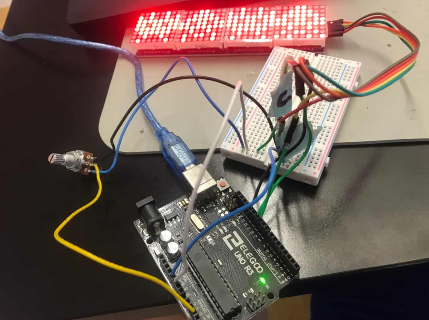
Because the 5V and ground pins were already occupied by the LED, I had to use a breadboard.
A breadboard makes it possible to wire both the LED and the potentiometer to 5V and ground.
With the potentiometer wired, I had to find a way to read the values.
I found and modified a code to show the values of the potentiometer in the serial monitor.
With the exception of the very start, there were not any major setbacks to achieving this milestone.
I learned a lot from this part of the project.
I found out more about how potentiometers and breadboards work, in addition to how and when they are used.
My next objective is to wire the second LED matrix, upload the pong code, and to build a controller.
Figure 1: LED wired to Arduino
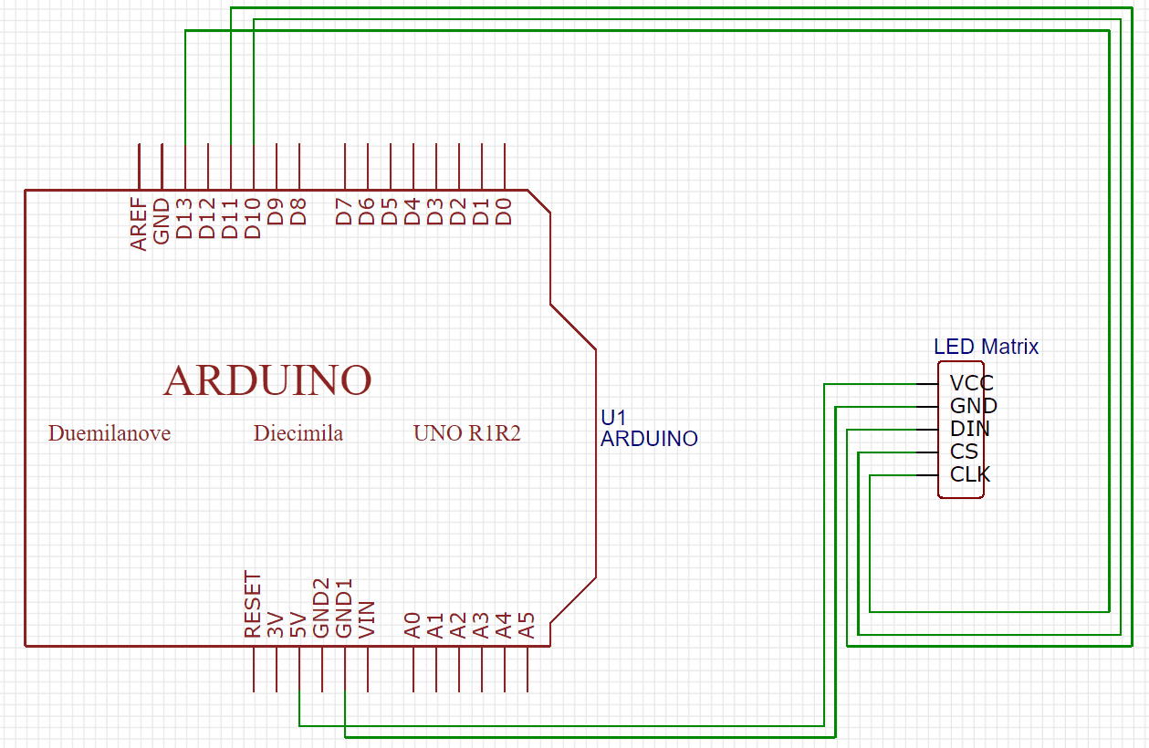
Figure 2: Working LED display

Figure 3: Project after first milestone
// Source: https://playground.arduino.cc/Main/LedControl/
#include "LedControl.h"

LedControl lc=LedControl(11,13,10,4); // Pins: DIN,CLK,CS, # of Display connected

unsigned long delayTime=200; // Delay between Frames

// Put values in arrays
byte invader1a[] =
{
B00011000, // First frame of invader #1
B00111100,
B01111110,
B11011011,
B11111111,
B00100100,
B01011010,
B10100101
};

byte invader1b[] =
{
B00011000, // Second frame of invader #1
B00111100,
B01111110,
B11011011,
B11111111,
B00100100,
B01011010,
B01000010
};

byte invader2a[] =
{
B00100100, // First frame of invader #2
B00100100,
B01111110,
B11011011,
B11111111,
B11111111,
B10100101,
B00100100
};

byte invader2b[] =
{
B00100100, // Second frame of invader #2
B10100101,
B11111111,
B11011011,
B11111111,
B01111110,
B00100100,
B01000010
};

byte invader3a[] =
{
B00011000, // First frame of invader #1
B00111100,
B01111110,
B11011011,
B11111111,
B00100100,
B01011010,
B10100101
};

byte invader3b[] =
{
B00011000, // Second frame of invader #1
B00111100,
B01111110,
B11011011,
B11111111,
B00100100,
B01011010,
B01000010
};

byte invader4a[] =
{
B00100100, // First frame of invader #2
B00100100,
B01111110,
B11011011,
B11111111,
B11111111,
B10100101,
B00100100
};

byte invader4b[] =
{
B00100100, // Second frame of invader #2
B10100101,
B11111111,
B11011011,
B11111111,
B01111110,
B00100100,
B01000010
};

void setup()
{
lc.shutdown(0,false); // Wake up displays
lc.shutdown(1,false);
lc.shutdown(2,false);
lc.shutdown(3,false);
lc.setIntensity(0,5); // Set intensity levels
lc.setIntensity(1,5);
lc.setIntensity(2,5);
lc.setIntensity(3,5);
lc.clearDisplay(0); // Clear Displays
lc.clearDisplay(1);
lc.clearDisplay(2);
lc.clearDisplay(3);
}

// Take values in Arrays and Display them
void sinvader1a()
{
for (int i = 0; i < 8; i++)
{
lc.setRow(0,i,invader1a[i]);
}
}

void sinvader1b()
{
for (int i = 0; i < 8; i++)
{
lc.setRow(0,i,invader1b[i]);
}
}

void sinvader2a()
{
for (int i = 0; i < 8; i++)
{
lc.setRow(1,i,invader2a[i]);
}
}

void sinvader2b()
{
for (int i = 0; i < 8; i++)
{
lc.setRow(1,i,invader2b[i]);
}
}

void sinvader3a()
{
for (int i = 0; i < 8; i++)
{
lc.setRow(2,i,invader1a[i]);
}
}

void sinvader3b()
{
for (int i = 0; i < 8; i++)
{
lc.setRow(2,i,invader1b[i]);
}
}

void sinvader4a()
{
for (int i = 0; i < 8; i++)
{
lc.setRow(3,i,invader2a[i]);
}
}

void sinvader4b()
{
for (int i = 0; i < 8; i++)
{
lc.setRow(3,i,invader2b[i]);
}
}

void loop()
{
// Put #1 frame on both Display
sinvader1a();
delay(delayTime);
sinvader2a();
delay(delayTime);

// Put #2 frame on both Display
sinvader1b();
delay(delayTime);
sinvader2b();
delay(delayTime);

// Put #3 frame on both Display
sinvader3a();
delay(delayTime);
sinvader4a();
delay(delayTime);

// Put #4 frame on both Display
sinvader3b();
delay(delayTime);
sinvader4b();
delay(delayTime);

}
/*Source: https://www.arduino.cc/en/tutorial/potentiometer
/* Analog Read to LED
* – ----------------
*
* turns on and off a light emitting diode(LED) connected to digital
* pin 13. The amount of time the LED will be on and off depends on
* the value obtained by analogRead(). In the easiest case we connect
* a potentiometer to analog pin 2.
*
* Created 1 December 2005
* copyleft 2005 DojoDave <http://www.0j0.org>
* http://arduino.berlios.de
*
*/

int potPin = 2; // select the input pin for the potentiometer
int ledPin = 13; // select the pin for the LED
int val = 0; // variable to store the value coming from the sensor

void setup() {
pinMode(ledPin, OUTPUT); // declare the ledPin as an OUTPUT

Serial.begin (9600); // make sure the baud is set to 9600.
}

void loop() {
val = analogRead(potPin); // read the value from the sensor
digitalWrite(ledPin, HIGH); // turn the ledPin on
delay(100); // stop the program for some time. You can change the delay but if the delay is too low it may not work.
digitalWrite(ledPin, LOW); // turn the ledPin off
delay(100); // stop the program for some time

Serial.println(val); // displays the value of the potentiometer periodically in the serial monitor
}
Starter Project
My starter project was the Useless Machine.
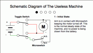
When the switch on the top is flipped, an arm pushes the flap on the top open and turns the switch off.
The switch supplies power to the motor.
The motor is attached to the arm, which causes the arm to move.
When the arm moves, it removes pressure from the microswitch.
When the arm reaches the top switch, the motor moves in reverse, which moves the arm in the opposite direction
When the arm returns to its starting position, it presses the microswitch again, which turns the machine off.
The first step was to solder all the required parts onto the printed circuit board, or PCB.
I was able to solder the switch and resistors with little trouble. The screw terminals ended up being slightly out of place, but my first real struggle was the LED, which changes color based on what direction the mechanism that flips the switch is moving.
I originally thought the LED went on the same side of the PCB as the other parts, but it actually did not.
By the time I noticed it was too late, and I had to desolder.
This process took a very long time and when it was finally done, I realized the LED would have been fine the way I originally soldered it.
After soldering a few more parts I moved on to screwing acrylic parts to the motor.
This part was very annoying because the acrylic parts moved around a lot.
This made it very difficult to screw them to the motor. At many points I had to use helping hands and tape.
WIth those parts attached, the next step was to attach the PCB to it.
I was able to complete this step by using the holes in the acrylic parts to firmly screw the PCB to the motor.
The next step was attaching the arm.
To do this, I put the required 3 AAA batteries and put them into the battery pack.
To connect the battery pack, I put the red and black wires in the screw terminal.
At first the wires fell out, but by soldering the tip I was able to keep them in place.
I spun the motor until it was in the correct position and screwed the arm on.
With the first test complete, I moved onto the final (and most tedious) step, building the box.
First, I attached the motor and PCB to the base of the box by fitting it into the slots on the base.
To keep the box slightly elevated, I added four silicon feet to the corners of the box.
I used velcro to keep the battery pack secure and aligned it with the nub on the motor
Next, I had to screw the corner pieces on the box.
The intended way of screwing these in was difficult, since the inside was not fully hollow, so I had to drill the screws in place.
The final step was putting the sides and top of the box together.
This part was tedious and annoying because the sides of the box kept moving around, and for the top of the box to fit on, everything needed to be in the perfect position.
With time and help, I was able to get it done.
Overall, this project had many annoying aspects.
To make this easier you need to take additional steps that the instructions don’t provide.
Screwing parts that move easily can get very frustrating, and even tape doesn’t help sometimes.
Despite this, I am still glad I chose this project because I learned that sometimes you need to think outside the box to complete a project.
This project helped me improve my soldering skills and made me more resourceful.
FIgure 1: Screwing acrylic parts onto motor

Figure 2: Attaching PCB to motor

Figure 3: Screwing the arm onto the motor

Figure 4: Screwing corner pieces into place


