About Me
Hi there! My name is Bella, and I am a rising sophomore in the Bay Area. Engineering became particularly interesting to me after going to the Maker’s Faire and doing various computer science projects at school (Lego Mindstorms & Making JavaScript/Python/HTML/CSS/Java Programs). I have been accustomed to being taught through step by step instruction. BlueStamp Engineering presented itself as an opportunity to learn through trial by error. I chose the MintyBoost Charger as my starter project because of its practicality and the Footissimo as my main project due to my yearning for a challenge. Please scroll down to see my Main Project, the Footissimo! 🙂
Reflection
I thoroughly enjoyed my three weeks at BlueStamp Engineering. Attending this program gave me the opportunity to scratch the surface of different kinds of engineering, such as electrical, mechanical, and computer science. I now have a greater skill set and confidence in myself. After being immersed in a ‘learn by doing’ environment, taking difficult problems and being able to solve them on my own by finding various resources has been ingrained in me. For that reason I will be forever grateful that I was able to attend BlueStamp Engineering. Being able to listen to the speakers (entrepreneurs, people who work in large companies, and the instructors) was a significant part of the program that made me feel inspired and motivated to continue my STEM studies. The college talk was also very beneficial, giving me an insight of the college experience and application processes. As a rising sophomore, I now have more knowledge regarding my preparations for college applications. I most definitely would like to pursue a career in the sciences, whether that may be engineering or another field. I couldn’t ask for anything more from BlueStamp Engineering! While my time at BlueStamp Engineering has concluded, I will still be making developments to the project and posting it here. Thank you!
Main Project
https://www.youtube.com/watch?v=zUzMBpm18I0
Overview
For my main project, I decided to create a Student Defined Project which I named the Footissimo (Foot+Fortissimo = Footissimo). An idea for a digital music stand that allowed users to write in music and sync them with each other was my music teacher’s idea. After I was given the opportunity to participate in BlueStamp Engineering, I decided to make a spin-off of her idea. The Footissimo includes a foot pedal that allows the user to turn pages in an Android application that I programed. The application has the capabilities of downloading sheet music and allowing the user to write in it and share the modified pages.
Milestone 2
Overview
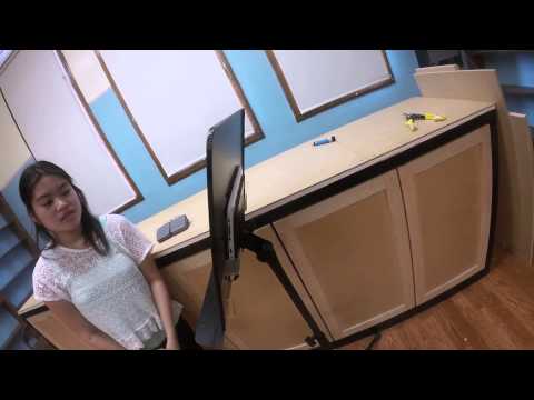
Although my initial plan for Milestone 2 was noted to be the completion of the Android application, it seemed more appropriate to cover the mechanical aspect that I completed during the week. An additional pedal was made and connected to the BlueFruit EZ-KEY HID via the purple wire. In order to connect the two pedals and battery holder, I cut the MDF (medium density fiberboard). The MDF replaced the acrylic glass that originally connected the foot pedal to the battery holder. The music stand went through a major transformation due to the cuts in the middle and parts that were hammered. After an orbital jigsaw was used to cut the stand, the bottom flap was bent to created a shelf. The metal flap was folded again an inch away from the previous fold, creating a 90° angle. Using a debur tool, I smoothed out the sides, preparing the metal to be covered in spline (super glue as the adhesive). In order to stabilize the tablet that would fit in the pocket, a laser cutter was used to create two rectangles (6″ x 1″) that would serve as brackets. The brackets were glued to the stand using epoxy. When using epoxy, make sure that the work area is well ventilated. You must wait five minutes for it to dry. I suggest using clamps as shown in the pictures below. Please take a look at the link for the MDF template. In addition to the mechanical build, I added a function to the last pin so that I could see if RETURN would have any effect on the premade PDF viewer. The updated picture of the GUI is below.


Challenges
- Using the orbital jigsaw – Make sure someone teaches you how to correctly use it. It was scary for me at first but with proper guidance and supervision, the task was completed and I had fun.
- “I am always doing that which I cannot do, in order that I may learn how to do it.” ~Pablo Picasso
- Figuring out how to glue the spline to the stand.- I wore gloves while using superglue; however, it ripped my gloves apart. Be very VERY CAREFUL.
- Just be careful!
- Drilling/Cutting the metal music stand. – The lead instructor did this for me, but for those of you who plan on attempting this…. Make sure that all the clamps are set properly and firmly.
- Set up a safe work environment.
Milestone 1
Overview
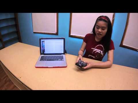
As of this milestone, I am able to wirelessly control my laptop with the foot pedal. In order to make the foot pedal Bluetooth, I disassembled a foot pedal from Adafruit, cut the serial cable, and rewired it, connecting it to the BlueFruit EZ Key HID (human interface device). The black wire from the foot pedal connects to ground (the reference point in an electrical circuit from which voltage is measured). The white wire connects to these pins that I remapped using a plugin development environment (.pde) and GUI (graphical user interface). See the picture below to look at the GUI. Now each pin is able to carry out a specific function that I assigned. The pins from left to right have these functions: Home, PageUp, PageDown, Play/Pause, VolumeUp, VolumeDown, LeftArrow, RightArrow, SPACE, BACKSPACE, Power. The last pin does not have a function. Please watch the video for a demonstration.

Graphical User Interface from the Plug-In Development Environment
How does it work?
The HID transmits data via low power radio waves. This computer picks up the signal using built-in Bluetooth or a Bluetooth dongle, an adapter that picks up Bluetooth signals and connects to the computer through a USB port. The Bluefruit EZ Key HID has a class 2 radio, giving the device a range of about 10 meters. To prevent interferences from unauthorized devices, it uses spread spectrum frequency hopping, the repeated switching of frequencies to minimize “electronic warfare”. The HID is connected to a battery pack containing 3 AAA batteries that charge the HID.
Challenge
- Soldering the individual pins – Use a helping hand and Be Patient!
- “Patience is not simply the ability to wait- it’s how we behave while we’re waiting.” ~Joyce Meyer
Starter Project
Overview
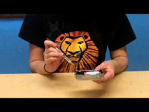
I made the ever practical MintyBoost Charger, developed by Adafruit, as my starter project. It is a portable charger placed in a Altoids Gum sized tin. The mechanical aspect was fairly simple (soldering all the parts onto the PCB – printed circuit board); however, much patience was needed to understand the concept of how it worked.
Parts

https://www.sparkfun.com/products/retired/9629
Parts can be bought at: https://learn.adafruit.com/minty-boost/parts-list
I would recommend buying electrical tape as well.
Cost of Starter Project (including electrical tape) ≈ $21.50
How it works
The MintyBoost is powered by two 1.5V AA Alkaline batteries. The 5V converter, an IC chip (integrated circuit), boosts the 3V to up to 5V, regulating the currents being transmitted to the device so that the MintyBoost can be compatible with multiple devices. The four capacitors store electrostatic currents and stabilize the voltages’ transition. Likewise, the inductors stabilize the currents’ transition and stores the energy in the form of a magnetic field. Five resistors (3 different types) were used in this project. The different types of resistors can be identified by the different color bands, which represent the amount of ohms (electrical resistance) a resistor has. One of the most important components is the diode, which permits a current to flow in only one direction and never the other. In this way, the batteries are able to charge the device rather than the device charging the battery.
Schematics from Adafruit
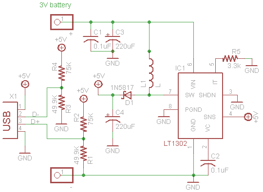
http://www.ladyada.net/images/mintyboost/mintyboostv3sch.png
Challenges
- Soldering the tiny parts- Use a helping hand to keep it steady
- The tin getting warm- Use electrical tape to prevent short circuiting
- Putting the resistors on the “wrong side” – NOTE There is no such thing as the wrong side…resistors have no polarity.
- Unintentionally cutting the wires too short instead of stripping them- Do not rush the process. Take your time.