Bluetooth Knee Monitor
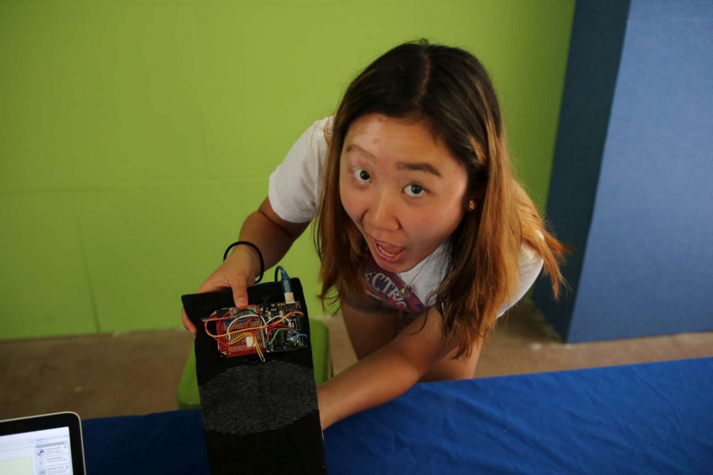
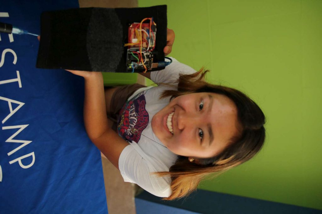
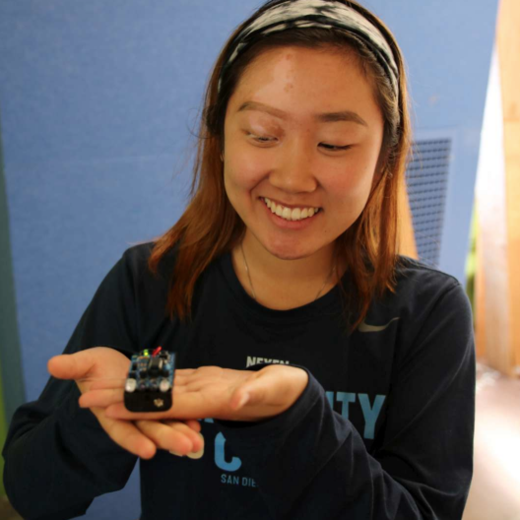
Hi, my name is Ashley and my project is the Bluetooth Knee Monitor, which uses a flex sensor, Arduino, accelerometer, and Bluetooth module to send information about how your knee is bending, accelerating and rotating. This device is useful because it can tell you if you’re bending your knee wrong and allow you to correct it.
Engineer
Ashley K
Area of Interest
Mechanical Engineering/ Aerospace
School
Evergreen Valley High School
Grade
12
THIRD MILESTONE
For my third and final milestone, I converted my data into 2 real-time graphs. At first, I tried to use Python in order to create the graphs, but because of the time crunch I was under, it seemed that Python graphs were going to take too long. Besides the time factor, I had to take time to figure out how to import the data incoming from Bluetooth to the Python terminal while also trying to fix the refresh rate of the graph, which wouldn’t show a continuous graph all in one window. Even when using the animate function, I found that in addition to the problem with the continuity, I also needed to use a smoothing algorithm in order to get smoother and more constant values. To do this, I used an exponential smoothing algorithm in the Arduino serial. Eventually, I realized that trying to graph with matplotlib and pyserial libraries would take too long, and after doing some web searching, I was able to find some online software called MegunoLink which was perfect for visualizing my data. It has everything for me in a graphic user interface, so all I needed to do was customize my settings and connect my Bluetooth HC-05 to the computer, in order for the program to receive it. I was also able to create live time graphs, customize the X, Y axes, and create a legend. Overall, I have to say this project challenged me in all sorts of ways. I came into BlueStamp not knowing anything about engineering. I didn’t know how circuits worked, what an Arduino was, or how to solder. But honestly, I’m so so so glad I applied to this program. Not only did I learn by doing, but I got to learn so much from the lecturers and instructors. I also meet a ton of amazing people and made some great friends.
Second Milestone
Click the link to expand image and see more!
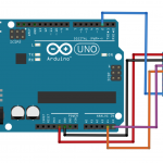
For my second milestone I basically connected an IMU sensor, the MPU6050, to my whole circuit board. Before doing this, I had to add some additional wiring to connect the MPU6050 to the Arduino, using an I2C connection in order to allow the accelerometer to send data to the Arduino. An I2C connection is a type of “master-slave” connection, a connection allowing for multiple devices to be under the control of one single device. In order to create this connection, I had to follow a schematic I had found online. With this, I didn’t need a voltage divider, instead of being able to input the VCC of the MPU6050 into the 3.3 V. After connecting it all up through wiring, I had to upload the code for the accelerometer into the Arduino. Using Arduino Serial, I uploaded the MPU6050 code into serial and changed all the “Serial”s to “my.Serial” in order to get it to upload to Bluetooth Serial Terminal. Afterward, I really only wanted to get the bend degree values and not the resistance on the graph. So, I commented out the line that prints out and calculated the values for resistance. Of course, while I did this, I had to do constant recalibration and editing of the code throughout the whole process, which proved to be the most challenging part. First, I kept getting FIFO overloads, and the IMU sensor code would not print out the code to calculate the values for ypr (yaw, pitch, roll). After taking out the delay time and changing the baud rate, I was able to lessen the number of times I received FIFO overloads and get the code to calculate the needed to values. Fixing the small little bugs and glitches within the code that caused it to not send over the values took a significant amount of time, but after getting it all fixed, I was finally able to get on with the real-time graph.
First Milestone


Code Used for Flex Sensor, Click for link to Github!
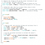
My first milestone was connecting the flex sensor to my Arduino then having the Bluetooth module send the data wirelessly to my computer. Admittedly, this process was probably the longest and toughest for me, just because I had to learn a lot about how circuits work, how a breadboard works, and coding in Arduino Serial.
My first order of business was to connect my flex sensor to the Arduino. A flex sensor is a variable resistor, whose resistance increases the more it’s bent. When the substrate inside the flex sensor is bent, the sensor produces a resistance output correlated to the bend radius. When the radius is smaller, the resistance increases. In order to connect the flex sensor in a circuit, I had to learn about voltage dividers, which controls a large voltage input and turns it into a small output. This mechanism, based on Ohms Law, helps the Arduino read the information from the flex sensor. I then used the code I found on Sparkfun and edited it to fit my purposes (ie calibrating the resistance values to get the correct bend values).
In addition, I had to connect the Bluetooth module HC 05 to the Arduino to get my data to send wirelessly. Using a library called Software Serial, I had to change the RX (receiving)and TX pins(transmitting) from the digital pins to pins 10 and 11 in order to allow the Bluetooth and computer to communicate with each other. Doing this opens to the two serial enabled devices and adds serial ports. After that, I had to do another voltage divider, to control the amount of voltage going into the Bluetooth’s RX pin. Afterward, I downloaded Bluetooth Serial Terminal and got the data to appear on the computer.
Starter Project:TV B Gone!
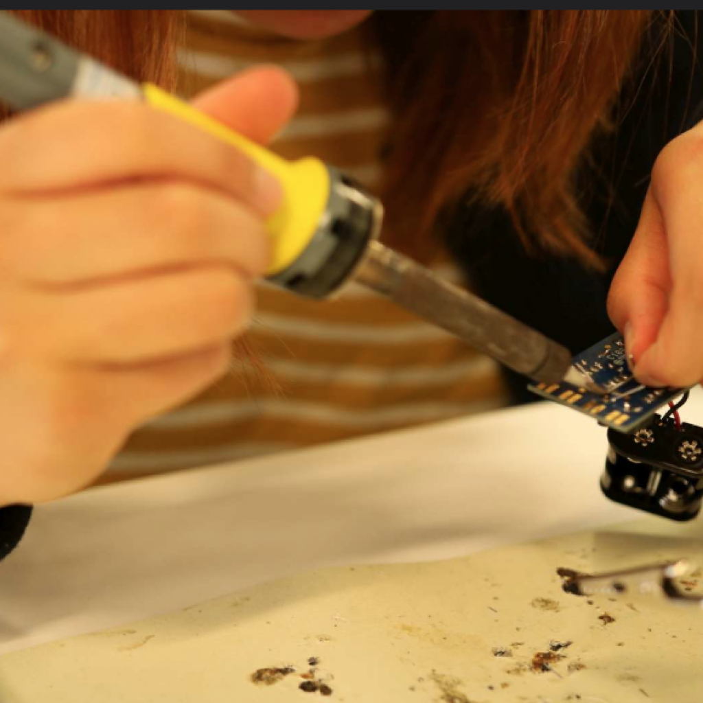
For my starter project, I decided to do the TV B Gone, which is a small universal remote that has the ability to shut off any TV through infrared light waves. Most remote controls for electronic devices operate with invisible infrared light, usually about 940 nm, and picked up from an LED receiver in the designated object. My project works with the same mechanics, using the LED’s at the top, the small bulbs emit pulses of infrared light, and when pointed at a TV, has the capacity to send a signal to shut the TV off. With the little microcontroller, the TV B Gone has the ability to send specific wavelengths through pulses, which will shut off a TV depending on the wavelength the TV operates on. From this project, I learned a lot about the hardware aspect of things, such as the purpose of resistors, what soldering was and how to do it. I think the part I enjoyed the most about the project was that I had the ability to learn and develop new skills. For me, I definitely enjoyed soldering, and plus I learned something new about how remote controllers actually work, spoiler, it’s not magic 🙁