Third Milestone
My final milestone was to get all parts working.
The way it works is the potentiometers send a PWM signal to the servos by the code in the Arduino.
A PWM is a Pulse Width Modulation, which reduces the amount of power delivered by an electric signal.
It’s a lot like my first milestone except with 4 servos and I duplicated the code for those 4 servos.
The 4 servos control every axis of movement available on the arm.
The arm can rotate 180 degrees. It can move a forearm and an upper arm, and it also has a claw, used to grab things.
I ran into an immense amount of issues, only some of which are human error.
Some parts that I made errors in were the wiring, soldering, and an overall lack of knowledge on the subject of polarity.
However there were many issues with the resistance of the breadboard and the torque of the servos
Eventually I ended up with a solderless breadboard design. See figure below for accurate representation
There was not enough power in the Arduino alone so I used a power supply.
Here are the steps I took
1: Soldering potentiometers to wires and trying to figure out how a PCB works
2: Soldering potentiometers on to pcb, scrapping that idea
3: Soldering potentiometers onto a polarized PCB
4: Soldering potentiometers onto a polarized PCB. Idea scrapped.
5: Using a solderless breadboard on an Arduino attachment.
6: using a solderless breadboard on an Arduino attachment. Idea scrapped
7: New potentiometers, deciding on just using a solderless breadboard.
8: Finishing main project.
This project took a lot of thinking and ideas to finish.
Thank you for coming to my website and taking a look at the things I’ve been up to.
Wire Schematic
Yeah mhm yeah oh yeah

Second Milestone
My second milestone was to assemble my arm.
It was a relatively easy process however I did encounter issues along the way.
It does not work electrically however it looks and for the most part works the way an excavator would work, but with 1 added joint.
Each component of the arm plays an important part in the arm’s movement.
One servo imitates an upper arm while a different servo imitates the forearm.
One servo acts like a grabber while another one rotates the entire arm 180 degrees.
One of the issues I encountered during building the arm was the servo arms holes being too small to fit screws into.
I solved that issue by using a drill to widen the holes in the arms.
I also experienced some minor issues screwing the bolts in, because they would always fall out due to the angle they were supposed to be installed in.
For the bolts I decided to screw them in with one hand and hold it with the other, instead of screwing with one hand and holding the part itself.
While building the mechanical part of my arm, I learned how to follow an instructional video, the importance of different screwdriver sizes, and now careful I need to be with my parts.
First Milestone
My first milestone was to get one servo working with a potentiometer.
A servo is essentially a motor but it is limited to a certain amount of degrees of movement. A potentiometer is an analog input device which is also limited to 180 degrees of movement.
What happens when the potentiometer is rotated in a specific direction is that the servo also rotates in that direction. The data from the potentiometer is transferred from the yellow wire into an analog input on the arduino. The code on the arduino relays that information to the analog output, which happens to be the servo in this case.
The code was the knob example code from the arduino desktop application.
I had initially thought I needed to write a value, because I assumed that “(value)” was a placeholder for a certain number.
I would soon learn that I was incorrect, and the “(value)” was previously classified as a variable and was not a placeholder.
I encountered a couple of issues along the way.
I was unaware how my wiring was supposed to work, which ended up in lots of frustration.
But upon further analysis from the diagram provided on the arduino website, as well as guidance from the teachers, I was able to do my wiring correctly, and finish the milestone.
During this project, I learned how valuable the arduino examples are, and I also learned how to use an analog input to control something.
Starter Project
Demonstration
Documentation
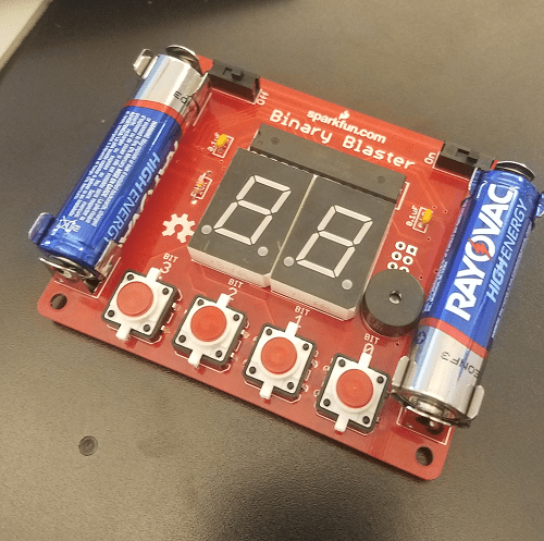
My starter project is the sparkfun.com binary blaster.
It teaches binary to the user by using a Numerical display and a microcontroller.
It’s buttons represent 1, 2, 4, and 8 in binary.
The user is quizzed on their knowledge of binary, and the machine teaches binary by going through a demo before the game starts. The numerical display displays the numbers in decimal while the buttons and LEDs go through the numbers in binary. The demo consists of numbers 1 to 15 in binary.
One: 0001
Two: 0010
Four: 0100
Eight: 1000
A lit button represents one, and an unlit button represents zero.
A number shows up on the numerical display, and it is the user’s job to convert that number into binary using the buttons.
It comes complete with battery functionality and sound using a piezo buzzer.
The binary blaster is definitely an entry level project, however it teaches the importance of soldering and polarity nonetheless, I also learned binary after finishing the project.
I did not make any mistakes during this project because I was extra cautious with my materials due to the issues I encountered during a previous project.


