Voice Controlled Robot
I’m making a robotic car that moves around and can be voice controlled through an Android phone. I chose this project to learn more about incorporating software and hardware in one product.
Engineer
Arthur Z.
Area of Interest
Mathematics
School
Lowell High School
Grade
Incoming Senior
Reflection
My time at BlueStamp was both enjoyable and irritating at times. The planning and physics of the project were fun, and seeing it work was definitely cool. However, there’s always these tiny problems that take a rather long time to pinpoint and correct, like loose wires.
I’ve learned a lot at BlueStamp. I’ve learned that most questions can be answered with a cursory Google search, and that questions that can’t can usually be solved through trial and error or guesswork.
Modification Milestone 1
For my modification, I’ve added LEDs and removed the battery pack. The battery pack had originally powered the motors, so I had to find a way to allow the universal charger to power both the Adafruit Huzzah and the motors. I used a 2 headed usb cable and a breakout board to do that.
Adding the LEDs on was simple. I got 2 NeoPixel LEDs to give turning signals. I first tested the NeoPixels on another breadboard with an Arduino Uno. The first time I tested the NeoPixels, I forgot to add a resistor and the thing exploded. Fortunately, that incident wasn’t repeated and I got the LEDs to work with the robot.
Next, I plan to get the robot to move in an arc. Currently, it only goes forward, backward, or pivots. I originally planned to give the robot sensors, but I dropped that plan due to time constraints.
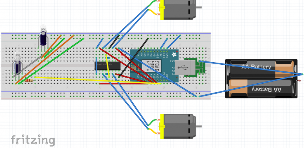
voice controlled robot schematic
Links: Code with modification 1
Final Milestone
My project is the voice controlled robot. The code for the robot is written in the computer and then transmitted to the Adafruit Huzzah. I’ve coded an app on an Android phone with MIT App Inventor. When I give the phone a voice command, it sends a signal to the Huzzah, which is powered by a universal charger taped on the bottom of the chassis, which then sends varying voltages to the H-Bridge. The H-Bridge controls the current from the battery pack to the motors which then turn on or off. It not only controls the magnitude of the current, but also the direction, which allows the engine to change direction.
My final milestone was coding the app and getting it to connect to the Huzzah. I had to first get an Android phone, since MIT App Inventor is only available on Android app stores. After I coded the app, it couldn’t connect to the Huzzah over the local wifi, so I had to make a hotspot on my phone.
I plan to modify the project by adding LEDs with neopixels to signify what the robot will do next.
Links
Milestone 1
My first milestone was getting the Adafruit huzzah to control the motors. I first used a NodeMCU, but it turned out to broken, so I switched to an Arduino Uno as a stop gap measure until I acquired an Adafruit Huzzah, which could connect to a device through Wifi. However, the code in the manual didn’t really work because I had a different number of pins, so I had to change up some of it.
Currently, I need a computer to upload code to the huzzah. The huzzah then runs the code and sends varying voltages to the H-Bridge, which tell it to do different things. The H-Bridge then controls the DC motors. My next step is to create my app and then connect it to the Adafruit Huzzah.
Link: Instructions
TV-B Gone
TV’s are turned on or off by specific infra-red signals. The TV-B Gone simply emits the right infra-red signal to turn the television off. However, not all televisions use the same signal, so the TV-B Gone has a database that stores many different off codes. When the TV-B Gone is activated, it starts shooting off these signals. There’s lots of TV off codes, so it could take up to 69 seconds for the right code to be emitted.
When the button is pressed, electricity is allowed to flow through the circuitboard and the capacitors monitor the voltage. When a voltage is applied, the transistors allow current to pass to the infrared LEDs. The LEDs then emit infrared light in specific patterns stored in the microchip. The oscillator oscillates at 8 mega hertz and acts as a timer to synchronize the flashing of the LEDs. To ensure that there isn’t a short circuit, resistors limit the current.
Creating this project was much more challenging than I anticipated. I made several notable errors. First, I soldered on the wrong resistor. I attempted to desolder it and accidentally desoldered a wire instead(the wire was in the right place). After that, I couldn’t correctly desolder anything else. The only solution was to cut off the incorrectly placed resistor and solder on the right resistor onto the leads of the wrong resistor. Then I also had to solder on the wire that I’d accidentally taken off. Afterwards, I tested the device. Unfortunately, there was a short circuit and I almost fried the batteries. They were too hot to touch, so pliers had to be used to yank them out. It turns out that I soldered two legs of the same capacitor so they touched, which caused the short circuit. I used a pair of pliers to pull apart the legs, and that fixed the last significant problem.
Link: Schematic for TV-B Gone
