
Neopixel Connect 4 Game
Engineer
Archie S
Area of Interest
Game Design / Engineer
School
Trevor Day High School
Grade
Incoming Junior
Reflection
I really enjoyed the time that I spent at BlueStamp. The counselors were all super nice and helpful. The working environment was top notch and had everything that I needed to complete my project, which I’m happy to say now works perfectly. I would definitely recommend BlueStamp for anyone is considering it, and I hope to do it again next year.
Second Milestone
What My Project Is/Does
My project is a digital LED Connect 4 Game using Neopixels, a breadboard, 3 tact switches with button tops, wires, jumper wires, a 3 AA Battery Pack and 3 AA Batteries and an Arduino. My final milestone in particular was to build a board for the Neopixel Board to stand on and for a place for the breadboard, Arduino and battery pack to be placed. Working towards my second milestone, I made a sketch of a cardboard frame to cut out and place the Neopixel board on When sketching, I took into account the measurements of the Neopixel board, how wide the breadboard was, how long it was, how long the triangle supports in the back had to be, how much space the wires had to go from the breadboard to the Arduino, from the Neopixel board to the Arduino and from the Neopixel board to the battery pack. I eventually made a board that was in total, 7.25 inches wide and 7.325 inches tall. I used about 1-inch margins between the sides and cuts of the board. I cut the board out using an exacto knife and a ruler to better trace my cuts. In addition I cut out holes for the wires in the back of the cardboard base for the wires in the back of the Neopixel board. From there, I taped with duct tape any additional wiring that was crowding the back of the machine to the cardboard backboard. I also used some pencils to support the cardboard backboard, and prevent it from falling forward or backwards. After I finished the modifications of my cardboard backboard, I made a base out of wood. I measured it and it was about 5 inches wide and 8 inches long. From there I hot glued the cardboard board to the wooden base. After that I hot glued the battery pack to wooden base. I then peeled off the part of the breadboard that kept the sticky part to be revealed. I then stuck the breadboard to the base. I drilled holes in the wooden base for the screws that went through the Arduino, keeping it attached to the base and keeping the game together.
I go further into detail about the project in my first milestone summary.
What I Learned
I learned that making the physical hardware is difficult, and can easily be manipulated by any error. However, I learned how to make an electronics project by itself.
Second Milestone Video


First Milestone
What My Project Is / Does
My Project is a Connect 4 Game. My first milestone was to install the code onto my game, work out any problems I may come across in setting up the game and to have it ready for when I build the hardware. When the game starts up, player one’s chip lights up its LED red, in the top right corner. Player one uses the three buttons to move and drop their chip in the right column. The player uses the left button to move the chip left, the right button to move it right, and the middle button to drop the chip in the desired column. After player one finishes their first turn, a blue LED lights up in the top left corner signifying that it is player two’s turn. Player two uses the same buttons to move the chip left and right, and eventually drop the chip in the wanted column. This process repeats over and over again, with the players taking turns and the chips stacking up until a player gets four chips in a row. The first person to get four chips in a row wins the game. The players can get four chips in a series of patterns, including vertical, horizontal or diagonal. After a player wins a game, all of the LEDs lit up, flash a couple of times, then look as if they drop off the bottom of the game. So the second to the bottom row of lit-up LEDs become the bottom row and so on until there are no chips left on the board. After a second, the game restarts, and once again a red light appears, signifying that it is player one’s turn again. Also, there’s a demo mode that plays every time a button is not pressed long enough, dropping chips automatically and randomly. This continues until four chips in a row line up and the demo restarts. The Connect 4 game for my final project was inspired by the real-life version of the game by Hasbro. I found the final project idea on a post by a person with the username botdemy, on a website called Instructable Circuits. As a person with only two weeks at Blue Stamp and only a little more than a week to work on my final project, the post was really helpful for me and I recommend using the website for any future project ideas. The Connect 4 game is made from an Arduino Elegoo Uno R3, a half-sized breadboard, three AA batteries and battery pack, 8 wires, 2 alligator clips, 2 male jumper wires, 3 tact switches (the buttons), and a WS2182B 8×8 Neopixel Board.


What I Learned
Before BlueStamp I had little to no experience with Engineering concepts, lingo, devices. This project was really educative and helpful in my journey to learn more about the coding, electrical and building aspect of engineering. During the assembly of my final project, I learned about pull up resistor circuits, in which the connection of a switch, grounds the current, and sends information to the Arduino about whether or not the button is being pressed. During this project I learned about Arduinos. I learned parts of the Arduino, and to never connect two power sources at the same time. I also learned about the importance of connecting the correct pins and wires. I learned all about adafruit 8×8 Neopixel boards. Specifically that each LED has a value, and that the Connect 4 game code was dependent on the value that the pixels had. Because I got a different Neopixel board model, the WS2182B instead of the WS2182, the pixel values went up in a serpentine order, rather than the standard right to left. The code that I used for my game was intended for another kind of Neopixel board, the WS2182. I learned about the usefulness of male and female jumper wires. I learned a few things about how to specifically code for arduinos, like the syntax, specific libraries and setting a transpose array that reset the values of the LEDs.
Complete Overview


How It Works
WS2182B 8×8 Neopixel Board:
The WS2182B 8×8 Neopixel Board was probably the most important piece in assembling, with it being the place where the game takes place. My Neopixel board is essentially 64 LEDs, bunched together to make an 8×8 square of LEDs. The code allows for specific LEDs to light up in patterns to give a sense of the LEDs moving. On the back, 3 groups of wires connect to various places that help the game work. The first group of wires connects to the Arduino. The DIN wire which stands for ‘Data IN’. This wire takes information that the Arduino sends it to light up certain LEDs on the Neopixel board. The DIN wire connects to the 8-pin on the Arduino. The GND wire stands for ‘ground’. This wire’s connection to GND pin on the Arduino is a reference point for all signals, a place from which electrical current can be measured. The last wire in the first grouping on the Neopixel is the 5V wire which connects to the 5V pin on the Arduino. This wire supplies the Arduino with around 5V of electricity. The second group of wires is very similar to the first group however they don’t have a Data IN wire. This group of wires is meant to connect to the batteries and battery pack to supply the game with power. With alligators clips connecting them, the wires do just that. The third and final group of wires on the back of the Board is the same as the first, with a 5V wire and a GND wire, except it has a DOUT, or ‘Data Output’ wire, which would only be used if I were to connect more than one Neopixel boards together by connecting the input wires of the second board and the output wires of the second board. The LEDs on the front side of the Neopixel board are controlled by the information that the Arduino sends them.
Arduino:
The Arduino is the brain of the machine, distributing the voltage that it receives, taking in the input from the buttons, and receiving/giving information important for the functionality of the game. In the Arduino, the DIN wire from the Neopixel board is plugged into the 8-pin. In the code of the game, the 8-pin on the Arduino was classified as the pin that would send the Neopixel board, the input values of the button, and tell the board to light up certain LEDs. The line of code is #define PIN 8 before the setup function. When it came time to download the code to the Arduino I plugged in a USBC to USB converter into my Apple computer. Then I plugged in the Arduino wire to my USB input and into the complementing spot on the Arduino. I had to make sure that the Arduino program had the correct port type and board type before I downloaded my code. When I did download the code I had to shut off the battery pack because as I learned previously, there should never be two power sources connected to the Arduino, otherwise it could fry.
Tact Switch Buttons, The Breadboard, and The Circuit:
Above the 8-pin in the 9-pin, 10-pin and 11-pin are the wires that connect the buttons to the Arduino. The buttons used in this game are Tact Switches with colorful caps to differentiate them. They are connected into various spots on a half-sized breadboard. The first button that moves the LED chip to the right, is connected to the pins 8D, 10D, 8G, and 10G on the breadboard. The second button that drops the LED chip to the most-bottom spot in their column, is connected to the pins 15D, 17D, 15G, and 17G on the breadboard. The third button that moves the chip to the left, is connected to the pins 22D, 24D, 22G, and 24G on the breadboard. When the tact switches are untouched, they have about 5V flowing through them. Whenever the tact switches are pressed, the current flow to them is cut, with zero volts flowing through them. When the tact switches are pressed, they complete a circuit that grounds the current flowing, making there zero volts flowing through the circuit. When a change of voltage occurs/whenever a button is pressed, the input is sent to the Arduino via the pins connected, basically alerting the Arduino that the button has been pressed. Taking in this input from the breadboard, the Arduino uses the code installed and sends directions to the Neopixel board to adjust the LEDs, according to the data that the Arduino received from the breadboard. The male jumper wire that connects to the 9-pin on the Arduino connects to the 10C pin on the breadboard, which is in the same terminal strip as pin 10D, one of the pins that the right button is connected to. The male jumper wire that connects to the 10-pin on the Arduino connects to the 17C pin on the breadboard, the same terminal strip as pin 17D, one of the pins that the middle button is connected to. The male jumper wire that connects to the 11-pin on the Arduino connects to the 24C pin on the breadboard, the same terminal strip as pin 24D, one of the pins that the left button is connected to. Also, wires connect 22C (left button) to the most left spot, 15C (middle button) to the second most left spot and 10C (right button) to the third most left spot, on the most middle section of the negative rail. Just to the pin that’s to the right of these wires on the negative rail is a wire that connects to a GND pin on the Arduino. This wire is the one that’s responsible for the loss of current when a button is pressed by momentarily sending the current to a grounding pin on the Arduino.
Essential Code
All Of The Standard Code Required For Any Project Requiring an 8×8 Neopixel Board
#include <Adafruit_NeoPixel.h>
#ifdef __AVR__
#include <avr/power.h>
#endif
#define PIN 8 //arduino pin
#define NUMPIXELS 64 //# of pixels
Adafruit_NeoPixel pixels = Adafruit_NeoPixel(NUMPIXELS, PIN, NEO_GRB + NEO_KHZ800);
#ifdef __AVR__
#include <avr/power.h>
#endif
#define NUMPIXELS 64 //# of pixels
Transpose Funtion
The following code transposes the LED values, changing the order of them from a sequential serpentine pattern, back to the standard right to left pattern
int transpose [] = {
0, 1, 2, 3, 4, 5, 6, 7,
15, 14, 13, 12, 11, 10, 9, 8,
16, 17, 18, 19, 20, 21, 22, 23,
31, 30, 29, 28, 27, 26, 25, 24,
32, 33, 34, 35, 36, 37, 38, 39,
47, 46, 45, 44, 43, 42, 41, 40,
48, 49, 50, 51, 52, 53, 54, 55,
63, 62, 61, 60, 59, 58, 57, 56};
0, 1, 2, 3, 4, 5, 6, 7,
15, 14, 13, 12, 11, 10, 9, 8,
16, 17, 18, 19, 20, 21, 22, 23,
31, 30, 29, 28, 27, 26, 25, 24,
32, 33, 34, 35, 36, 37, 38, 39,
47, 46, 45, 44, 43, 42, 41, 40,
48, 49, 50, 51, 52, 53, 54, 55,
63, 62, 61, 60, 59, 58, 57, 56};
Sets The Button’s Arduino Pins
#define LeftButton 9 //data pin for left button
#define DownButton 10 //data pin for down buttonm
#define RightButton 11 //data pin for right button
#define DownButton 10 //data pin for down buttonm
#define RightButton 11 //data pin for right button
MISTAKES
The Connect 4 game that I used to model my game after used a different brand of Neopixel board than I ordered. As such the code for vertical and diagonal matching was screwed up. The arduino thought that 4 chips, with 2 chips in opposite rows were connected. Together with an instructor, we set up a transpose array to change the value of the pixels so that they matched those of the WS2182 model. When I initially setup the buttons, they weren’t pushed enough into the breadboard. This caused the buttons to fall the breadboard if the board was moved, in addition to the buttons not actually cutting the current from a circuit/sending the ‘if pressed’ information to the arduino. I solved this problem by pushing the buttons further into the board. In addition, the project of which I modeled my project from misplaced the jumper wires so that they connected to incorrect pins on the arduino. I fixed this by using common sense and adjusting the jumper wires’ positions. Another mistake that I made was that I accidentally left two power sources connected to my Arduino. This caused the Arduino to fry and I had to get a new Arduino. In connecting these wires to the Arduino, I found it difficult to keep them inside the Arduino, with the slightest movement of the Arduino resulting in them being unplugged. To remedy this, I soldered wires onto the end of the 5V, DIN and GND wires as extensions and from there I plugged them into the Arduino. This process, will make the hardware process easier, giving more space between the Arduino and the Neopixel board.
Starter Project
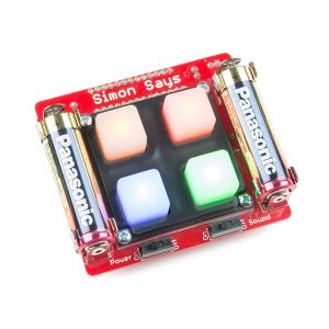
My Startup Project is a Simon Says Game. The player starts by holding down a button when all buttons are being lit up. From there, the game lights up specific buttons and tells the player to press the same buttons in the same order. If the player ever presses a button that wasn’t part of the pattern, or presses a button out of order, the button lights up in a sequence, signifying that the game has ended and that it’s ready to restart. The Buzzer on the back allows the player to use the game with sound, giving off a tune when the player presses a button or gets something wrong. As well, the player has the option of not playing with sound, with the turning off of the sound switch
How it Works
There were a lot of components to attach when I was building the game. I followed the given instructions and soldered a majority of the following components to my circuit board. There’s the starting Simon PCB board, which the game is put on. The 10K resistor regulates the flow of current. In addition it communicates with the microcontroller to not reset the game once the power is turned on. This way the game can continue to be played uninterrupted by loading lag. The 0.1µF Decoupling Capacitor help “clean up” the power on the board. The ATMega microcontroller is arguably one of the most important parts of the game because it’s here that all of the code for the simon game is held. Without this piece the game would not run. The Buzzer, provides the game with the option of hearing sound when a button is pressed or when the game is resetting. The LEDs also play a crucial part in the game because they light up and tell the player which buttons to press. In addition there are the battery clips, which strap down the AA Battery. The Side Switches determine whether the game is turned on or off and whether the player plays the game with sound or not. The Bezel serves the purpose of keeping the buttons in place. The standoff and screws attach the be
zel to the board. Standoff and screws offer a hand screwing option opposed to having screw the bezel to the board with a screwdriver. Button Pad forms the small rubber buttons of the game, which dictate which button is being pushed. Underneath the button pad there are insulating rubber circles, which, when pushed, cuts off current to the specific area underneath, giving the microcontroller the input of if the button is pressed or not.
What I Learned
While doing my startup project, I learned how to properly solder various pieces of machinery to circuit boards, a skill which I’m sure will be helpful for me in the future. I learned about the purposes of specific parts of machinery, such as microcontrollers and buzzers.
Mistakes
I had a few problems when building my game. There’s something wrong with my green LED, when it flashes randomly and screws up my game. The green button flashing happens every once in a while and other than that, my game works fine. I hadn’t fully soldered the battery clips to the circuit board and it seemed to screw up my game.
Mini POV Schematic
