Final Milestone
// these constants describe the pins. They won’t change:
const int xpin = A1; // x-axis of the accelerometer
const int ypin = A2; // y-axis
const int zpin = A3; // z-axis (only on 3-axis models)
//
int sampleDelay = 500; //number of milliseconds between readings
int motorPin=5;
void setup()
{
// initialize the serial communications:
Serial.begin(9600);
//
//Make sure the analog-to-digital converter takes its reference voltage from
// the AREF pin
pinMode(xpin, INPUT);
pinMode(ypin, INPUT);
pinMode(zpin, INPUT);
pinMode(motorPin, OUTPUT);
}
void loop()
{
int x = analogRead(xpin);
//
//add a small delay between pin readings. I read that you should
//do this but haven’t tested the importance
delay(1);
//
int y = analogRead(ypin);
//
//add a small delay between pin readings. I read that you should
//do this but haven’t tested the importance
delay(1);
//
int z = analogRead(zpin);
//
//zero_G is the reading we expect from the sensor when it detects
//no acceleration. Subtract this value from the sensor reading to
//get a shifted sensor reading.
float zero_G =512;
//
//scale is the number of units we expect the sensor reading to
//change when the acceleration along an axis changes by 1G.
//Divide the shifted sensor reading by scale to get acceleration in Gs.
float scale =102.3;
//
//Serial.print(((float)x – zero_G)/scale);
Serial.println(x);
// Serial.print(“\t”);
// //
// //Serial.print(((float)y – zero_G)/scale);
// Serial.print(y);
// Serial.print(“\t”);
// //
// //Serial.print(((float)z – zero_G)/scale);
// Serial.print(z);
// Serial.print(“\n”);
// //
// delay before next reading:
// read the value of the accelerometer:
int motorValue = analogRead(motorPin);
// if the analog value is high enough, turn on the LED:
if (x > 400) {
digitalWrite(motorPin, HIGH);
} else {
digitalWrite(motorPin, LOW);
}
// print the analog value:
Serial.println(motorValue);
delay(1); // delay in between reads for stability
}
First Milestone
Name: Anya Pabby
Location: New York City
Instructor: Sebastian Roubert
Starter Project: #11 Useless machine
Main Project: #115 Smart Dog Collar
Major Steps to complete the project:
- Make sure all parts have arrived as planned
- Draw a schematic that shows every wire that will need to be connected.
- Wire three vibrating discs and battery to the particle electron board- Milestone
- Make a pouch to hold board, discs, and battery (using sewing machine possibly).
- Write and test code that will make the dics vibrate- Milestone
- Attach pouch to the dog collar and test
- Create full documentation, write a blog post describing the system, and post everything on your webpage.- milestone
Potential Modifications:
- Wire sound sensor and/or speed sensor to arduino, write code for sensors and attach them to collar
| Vibrating mini motor disc | Adafruit | 1201 | 3 | $1.95 | |||
| Lithium ion polymer battery- 3.7v 1200mAh | Adafruit | 258 | 1 | $9.95 | |||
| Dog Collar | Amazon | 27552 | 1 | $8.78 | |||
| LM393 Speed Measuring Sensor Photoelectric Infrared Count Sensor DC 5V | Amazon | STK0114017571 | 1 | $2.75 | |||
| Arduino Uno R3 Microcontroller A000066 | Amazon | A000066 | 1 | $19.85 | |||
| Sparkfun Sound Detector | Sparkfun | 12642 | 1 | $10.95 |
const int xpin = A1; // x-axis of the accelerometer
const int ypin = A2; // y-axis
const int zpin = A3; // z-axis (only on 3-axis models)
//
int sampleDelay = 500;
void setup()
{
Serial.begin(9600);
//
pinMode(xpin, INPUT);
pinMode(ypin, INPUT);
pinMode(zpin, INPUT);
}
void loop()
{
int x = analogRead(xpin);
//
delay(1);
//
int y = analogRead(ypin);
//
delay(1);
//
int z = analogRead(zpin);
//
float zero_G =512;
//
float scale =102.3;
//
Serial.print(((float)x – zero_G)/scale);
Serial.print(“\t”);
//
Serial.print(((float)y – zero_G)/scale);
Serial.print(“\t”);
//
Serial.print(((float)z – zero_G)/scale);
Serial.print(“\n”);
//
delay(sampleDelay);
}
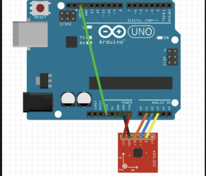
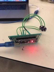
Arduino Board connected to the accelerometer
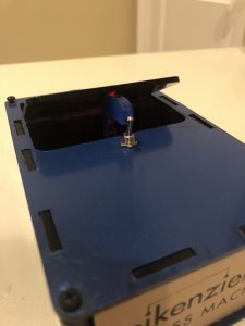
Starter Project
