CNC Plotter
This mini CNC plotter made from deconstructed DVD drives can draw anything from words to designs. With a similar design to a 3D printer, it has an x, y, and z axis
Engineer
Annika P.
Area of Interest
Engineering
School
Menlo School
Grade
Incoming Freshman
Materials


Major Steps to complete the project:
- Motors
- Make sure all parts have arrived as planned
- Get two stepper motors to work
- Disassemble DVD Drives
- Eject disk tray
- Disassemble parts
- use screwdriver
- Now have two stepper motors
- Also- save the DC motor with attachments for later
- Use multimeter to find which two wires correspond
- Cut the Kapton tape in 4 strands where the wires separate on each motors
- Solder 4 wires onto each of the strands on each of the motors
- Connect the wires using the wiring schematic
- Use arduino, two A4988 stepper motor drivers, half breadboard, and the 9v battery
- Run sample code to test if both stepper motors can run simultaneously
- Milestone
- X, Y, and Z Axis
- X axis
- Place on stepper motor with the rails on the big plexiglass piece
- Mark it with a pen in order to open the 4 holes for the screws
- Use triangle ruler to make sure that it is aligned
- Open the holes and mount the motor with nut screws
- On one side of it place the four mounting angles
- Mark it with a pen in order to open the 8 holes for the screws
- The distance between them should be 6mm
- Open the 8 holes on the plexiglass
- Screw the mounting angles into place
- Attach a base (either wood or cardboard or something) on X axis and place paper on top-(4x4cm)
- Y axis
- Place the other stepper motor on the two smaller plexiglass pieces
- Mark them with a pen in order to open the 4 holes for the screws
- Use triangle ruler to make sure that it is aligned
- Open the holes and mount the motor with nut screws
- Place it between the mounting angles
- Mark it with a pen in order to open the 4 holes for the screw
- Open the holes and screw the Y axis onto the X axis
- Z axis
- Use the DC motor with attachments from disassembled DVD drive parts
- Wire it to the breadboard and use tester code
- Attach it onto y axis with cardboard or any other base sideways so that it will be far enough out
- Attach pen onto attachment of DC motor with hose clamp
- Perfboard
- Solder everything that was on the breadboard onto a perfboard
- Milestone
- Code
- Arduino code
- Copy arduino code from https://create.arduino.cc/projecthub/Yogeshmodi/sketch-it-cnc-plotter-95019d
- Edit the code since I am using motor drivers instead of a motor shield and I am using a DC motor instead of a servo
- Download the code onto your ardino
- Processing
- Download Processing at https://processing.org/download/
- Get the GCTRL.pde code and example gcode files from http://www.ardumotive.com/new-cnc-plotter.html
- Press the arrow key to run it.
- Then press the p key and select the port
- Then press the g key and select a gcode file.
- Inkscape
- Download the 0.48 version of inkscape at https://inkscape.org/release/inkscape-0.48/?latest=1
- If on a mac download XQuartz here https://www.xquartz.org
- Download zip file to allow inkscape to convert into gcode https://github.com/martymcguire/inkscape-unicorn
- Control click inscape>show package contents
- Contents>resources>extensions
- Place all the contents of the src folder
- Printing
- Setup
- File>Document Properties> 4cm x 4cm
- Text
- Type anything within the dimensions
- Click on it
- Path>Object to Path
- Image
- Import image with transparent background
- Path>Trace Bitmap> Brightness Cutoff> update> ok
- Drag out the new path and delete the original image
- Drag the new path into the square
- Click on it
- Path> Object to Path
- Save
- File> Save As> select .gcode>Save
- Milestone
- Make sure all parts have arrived as planned
- Get two stepper motors to work
- Disassemble DVD Drives
- Eject disk tray
- Disassemble parts
- use screwdriver
- Now have two stepper motors
- Also- save the DC motor with attachments for later
- Use multimeter to find which two wires correspond
- Cut the Kapton tape in 4 strands where the wires separate on each motors
- Solder 4 wires onto each of the strands on each of the motors
- Connect the wires using the wiring schematic
- Use arduino, two A4988 stepper motor drivers, half breadboard, and the 9v battery
- Run sample code to test if both stepper motors can run simultaneously
- Disassemble DVD Drives
- Milestone
- X axis
- Place on stepper motor with the rails on the big plexiglass piece
- Mark it with a pen in order to open the 4 holes for the screws
- Use triangle ruler to make sure that it is aligned
- Open the holes and mount the motor with nut screws
- On one side of it place the four mounting angles
- Mark it with a pen in order to open the 8 holes for the screws
- The distance between them should be 6mm
- Open the 8 holes on the plexiglass
- Screw the mounting angles into place
- Attach a base (either wood or cardboard or something) on X axis and place paper on top-(4x4cm)
- Y axis
- Place the other stepper motor on the two smaller plexiglass pieces
- Mark them with a pen in order to open the 4 holes for the screws
- Use triangle ruler to make sure that it is aligned
- Open the holes and mount the motor with nut screws
- Place it between the mounting angles
- Mark it with a pen in order to open the 4 holes for the screw
- Open the holes and screw the Y axis onto the X axis
- Z axis
- Use the DC motor with attachments from disassembled DVD drive parts
- Wire it to the breadboard and use tester code
- Attach it onto y axis with cardboard or any other base sideways so that it will be far enough out
- Attach pen onto attachment of DC motor with hose clamp
- Perfboard
- Solder everything that was on the breadboard onto a perfboard
- Milestone
- Arduino code
- Copy arduino code from https://create.arduino.cc/projecthub/Yogeshmodi/sketch-it-cnc-plotter-95019d
- Edit the code since I am using motor drivers instead of a motor shield and I am using a DC motor instead of a servo
- Download the code onto your ardino
- Processing
- Download Processing at https://processing.org/download/
- Get the GCTRL.pde code and example gcode files from http://www.ardumotive.com/new-cnc-plotter.html
- Press the arrow key to run it.
- Then press the p key and select the port
- Then press the g key and select a gcode file.
- Inkscape
- Download the 0.48 version of inkscape at https://inkscape.org/release/inkscape-0.48/?latest=1
- If on a mac download XQuartz here https://www.xquartz.org
- Download zip file to allow inkscape to convert into gcode https://github.com/martymcguire/inkscape-unicorn
- Control click inscape>show package contents
- Contents>resources>extensions
- Place all the contents of the src folder
- Printing
- Setup
- File>Document Properties> 4cm x 4cm
- Text
- Type anything within the dimensions
- Click on it
- Path>Object to Path
- Image
- Import image with transparent background
- Path>Trace Bitmap> Brightness Cutoff> update> ok
- Drag out the new path and delete the original image
- Drag the new path into the square
- Click on it
- Path> Object to Path
- Save
- File> Save As> select .gcode>Save
- Setup
- Download the 0.48 version of inkscape at https://inkscape.org/release/inkscape-0.48/?latest=1
- Milestone
First Milestone

Second Milestone

Final Milestone

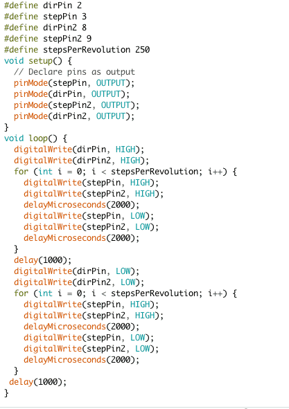
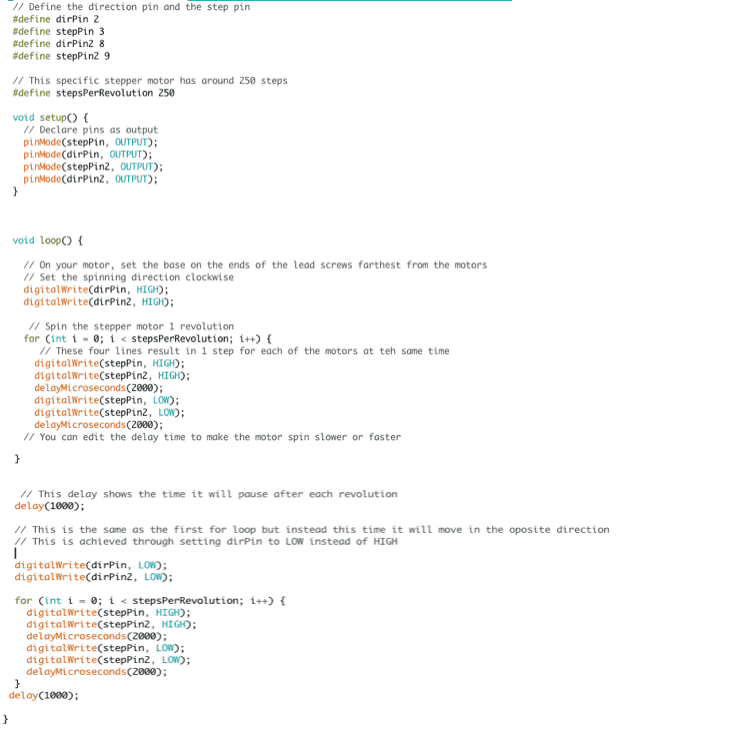
First Milestone Test Code (with or without comments)
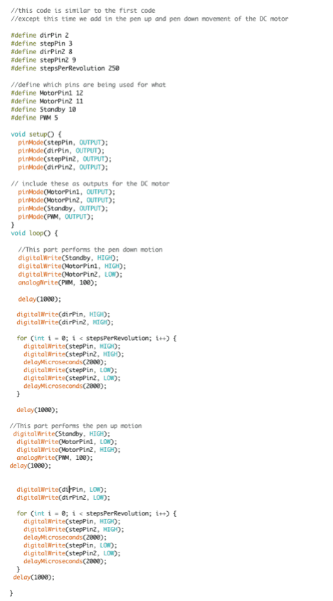
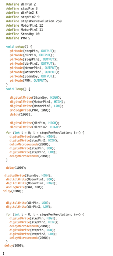
Second Milestone Test Code (with or without comments)
Download Arduino IDE here.
Download Inkscape here.
Make sure you download the 0.48 version.
For Macs, you will need to use XQuartz which you can download here.
Download the add-on for Inkscape here in order to convert the files into gcode.
There are instructions on how to install it into Inkscape below the download button.
Download Processing here.
Download the GCTRL.pde for Processing on this website.
http://www.ardumotive.com/new-cnc-plotter.html
You can also download example code files on that website.
Drawings Slideshow
Final Milestone
Wiring Schematic
Third Milestone
Download Inkscape here.
Make sure you download the 0.48 version.
For Macs, you will need to use XQuartz which you can download here.
Download the add-on for Inkscape here in order to convert the files into gcode.
There are instructions on how to install it into Inkscape below the download button.
Download Processing here.
Download the GCTRL.pde for Processing on this website.
http://www.ardumotive.com/new-cnc-plotter.html
You can also download example code files on that website.
#define dirPin 2
#define stepPin 3
#define dirPin2 8
#define stepPin2 9
#define MotorPin1 12
#define MotorPin2 11
#define Standby 10
#define PWM 5
#include <Stepper.h>
#define LINE_BUFFER_LENGTH 512
const int penZUp = 80;
const int penZDown = 40;
const int penServoPin = 6;
const int stepsPerRevolution = 20;
struct point {
float x;
float y;
float z;
};
struct point actuatorPos;
float StepInc = 1;
int StepDelay = 0;
int LineDelay = 50;
int penDelay = 50;
float StepsPerMillimeterX = 6.0;
float StepsPerMillimeterY = 6.0;
float Xmin = 0;
float Xmax = 40;
float Ymin = 0;
float Ymax = 40;
float Zmin = 0;
float Zmax = 1;
float Xpos = Xmin;
float Ypos = Ymin;
float Zpos = Zmax;
boolean verbose = false;
void setup() {
pinMode(stepPin, OUTPUT);
pinMode(dirPin, OUTPUT);
pinMode(stepPin2, OUTPUT);
pinMode(dirPin2, OUTPUT);
pinMode(MotorPin1, OUTPUT);
pinMode(MotorPin2, OUTPUT);
pinMode(Standby, OUTPUT);
pinMode(PWM, OUTPUT);
// Setup
Serial.begin( 9600 );
delay(200);
Serial.println(“Mini CNC Plotter alive and kicking!”);
Serial.print(“X range is from “);
Serial.print(Xmin);
Serial.print(” to “);
Serial.print(Xmax);
Serial.println(” mm.”);
Serial.print(“Y range is from “);
Serial.print(Ymin);
Serial.print(” to “);
Serial.print(Ymax);
Serial.println(” mm.”);
}
void loop()
{
delay(200);
char line[ LINE_BUFFER_LENGTH ];
char c;
int lineIndex;
bool lineIsComment, lineSemiColon;
lineIndex = 0;
lineSemiColon = false;
lineIsComment = false;
while (1) {
while ( Serial.available()>0 ) {
c = Serial.read();
if (( c == ‘\n’) || (c == ‘\r’) ) {
if ( lineIndex > 0 ) {
line[ lineIndex ] = ‘\0’;
if (verbose) {
Serial.print( “Received : “);
Serial.println( line );
}
processIncomingLine( line, lineIndex );
lineIndex = 0;
}
else {
}
lineIsComment = false;
lineSemiColon = false;
Serial.println(“ok”);
}
else {
if ( (lineIsComment) || (lineSemiColon) ) {
if ( c == ‘)’ ) lineIsComment = false;
}
else {
if ( c <= ‘ ‘ ) {
}
else if ( c == ‘/’ ) {
}
else if ( c == ‘(‘ ) {
lineIsComment = true;
}
else if ( c == ‘;’ ) {
lineSemiColon = true;
}
else if ( lineIndex >= LINE_BUFFER_LENGTH-1 ) {
Serial.println( “ERROR – lineBuffer overflow” );
lineIsComment = false;
lineSemiColon = false;
}
else if ( c >= ‘a’ && c <= ‘z’ ) {
line[ lineIndex++ ] = c-‘a’+’A’;
}
else {
line[ lineIndex++ ] = c;
}
}
}
}
}
}
void processIncomingLine( char* line, int charNB ) {
int currentIndex = 0;
char buffer[ 64 ];
struct point newPos;
newPos.x = 0.0;
newPos.y = 0.0;
while( currentIndex < charNB ) {
switch ( line[ currentIndex++ ] ) {
case ‘U’:
penUp();
break;
case ‘D’:
penDown();
break;
case ‘G’:
buffer[0] = line[ currentIndex++ ];
buffer[1] = ‘\0’;
switch ( atoi( buffer ) ){
case 0:
case 1:
char* indexX = strchr( line+currentIndex, ‘X’ );
char* indexY = strchr( line+currentIndex, ‘Y’ );
if ( indexY <= 0 ) {
newPos.x = atof( indexX + 1);
newPos.y = actuatorPos.y;
}
else if ( indexX <= 0 ) {
newPos.y = atof( indexY + 1);
newPos.x = actuatorPos.x;
}
else {
newPos.y = atof( indexY + 1);
indexY = ‘\0’;
newPos.x = atof( indexX + 1);
}
drawLine(newPos.x, newPos.y );
actuatorPos.x = newPos.x;
actuatorPos.y = newPos.y;
break;
}
break;
case ‘M’:
buffer[0] = line[ currentIndex++ ];
buffer[1] = line[ currentIndex++ ];
buffer[2] = line[ currentIndex++ ];
buffer[3] = ‘\0’;
switch ( atoi( buffer ) ){
case 300:
{
char* indexS = strchr( line+currentIndex, ‘S’ );
float Spos = atof( indexS + 1);
if (Spos == 30) {
penDown();
}
if (Spos == 50) {
penUp();
}
break;
}
case 114:
Serial.print( “Absolute position : X = ” );
Serial.print( actuatorPos.x );
Serial.print( ” – Y = ” );
Serial.println( actuatorPos.y );
break;
default:
Serial.print( “Command not recognized : M”);
Serial.println( buffer );
}
}
}
}
void drawLine(float x1, float y1) {
if (verbose)
{
Serial.print(“fx1, fy1: “);
Serial.print(x1);
Serial.print(“,”);
Serial.print(y1);
Serial.println(“”);
}
if (x1 >= Xmax) {
x1 = Xmax;
}
if (x1 <= Xmin) {
x1 = Xmin;
}
if (y1 >= Ymax) {
y1 = Ymax;
}
if (y1 <= Ymin) {
y1 = Ymin;
}
if (verbose)
{
Serial.print(“Xpos, Ypos: “);
Serial.print(Xpos);
Serial.print(“,”);
Serial.print(Ypos);
Serial.println(“”);
}
if (verbose)
{
Serial.print(“x1, y1: “);
Serial.print(x1);
Serial.print(“,”);
Serial.print(y1);
Serial.println(“”);
}
x1 = (int)(x1*StepsPerMillimeterX);
y1 = (int)(y1*StepsPerMillimeterY);
float x0 = Xpos;
float y0 = Ypos;
long dx = abs(x1-x0);
long dy = abs(y1-y0);
int sx = x0<x1 ? StepInc : -StepInc;
int sy = y0<y1 ? StepInc : -StepInc;
long i;
long over = 0;
if (dx > dy) {
for (i=0; i<dx; ++i) {
Xstep(sx);
over+=dy;
if (over>=dx) {
over-=dx;
Ystep(sy);
}
delay(StepDelay);
}
}
else {
for (i=0; i<dy; ++i) {
Ystep(sy);
over+=dx;
if (over>=dy) {
over-=dy;
Xstep(sx);
}
delay(StepDelay);
}
}
if (verbose)
{
Serial.print(“dx, dy:”);
Serial.print(dx);
Serial.print(“,”);
Serial.print(dy);
Serial.println(“”);
}
if (verbose)
{
Serial.print(“Going to (“);
Serial.print(x0);
Serial.print(“,”);
Serial.print(y0);
Serial.println(“)”);
}
delay(LineDelay);
Xpos = x1;
Ypos = y1;
}
void penUp() {
digitalWrite(Standby, HIGH);
digitalWrite(MotorPin1, HIGH);
digitalWrite(MotorPin2, LOW);
analogWrite(PWM, 100);
delay(1000);
Zpos=Zmax;
if (verbose) {
Serial.println(“Pen up!”);
}
}
void penDown() {
digitalWrite(Standby, HIGH);
digitalWrite(MotorPin1, LOW);
digitalWrite(MotorPin2, HIGH);
analogWrite(PWM, 100);
delay(1000);
Zpos=Zmin;
if (verbose) {
Serial.println(“Pen down.”);
}
}
void Xstep (int numstep) {
if (numstep < 0) {
numstep = abs(numstep);
digitalWrite(dirPin, HIGH);
}
else {
digitalWrite(dirPin, LOW);
}
for (int i = 0; i <= numstep; i++) {
digitalWrite(stepPin, HIGH);
delayMicroseconds(2000);
digitalWrite(stepPin, LOW);
delayMicroseconds(2000);
}
}
void Ystep (int numstep) {
if (numstep < 0) {
numstep = abs(numstep);
digitalWrite(dirPin2, HIGH);
}
else {
digitalWrite(dirPin2, LOW);
}
for (int i = 0; i <=numstep; i++) {
digitalWrite(stepPin2, HIGH);
delayMicroseconds(2000);
digitalWrite(stepPin2, LOW);
delayMicroseconds(2000);
}
}
#define stepPin 3
#define dirPin2 8
#define stepPin2 9
#define MotorPin1 12
#define MotorPin2 11
#define Standby 10
#define PWM 5
#include <Stepper.h>
#define LINE_BUFFER_LENGTH 512
const int penZUp = 80;
const int penZDown = 40;
const int penServoPin = 6;
const int stepsPerRevolution = 20;
struct point {
float x;
float y;
float z;
};
struct point actuatorPos;
float StepInc = 1;
int StepDelay = 0;
int LineDelay = 50;
int penDelay = 50;
float StepsPerMillimeterX = 6.0;
float StepsPerMillimeterY = 6.0;
float Xmin = 0;
float Xmax = 40;
float Ymin = 0;
float Ymax = 40;
float Zmin = 0;
float Zmax = 1;
float Ypos = Ymin;
float Zpos = Zmax;
boolean verbose = false;
void setup() {
pinMode(stepPin, OUTPUT);
pinMode(dirPin, OUTPUT);
pinMode(stepPin2, OUTPUT);
pinMode(dirPin2, OUTPUT);
pinMode(MotorPin1, OUTPUT);
pinMode(MotorPin2, OUTPUT);
pinMode(Standby, OUTPUT);
pinMode(PWM, OUTPUT);
// Setup
Serial.begin( 9600 );
Serial.println(“Mini CNC Plotter alive and kicking!”);
Serial.print(“X range is from “);
Serial.print(Xmin);
Serial.print(” to “);
Serial.print(Xmax);
Serial.println(” mm.”);
Serial.print(“Y range is from “);
Serial.print(Ymin);
Serial.print(” to “);
Serial.print(Ymax);
Serial.println(” mm.”);
}
void loop()
{
delay(200);
char line[ LINE_BUFFER_LENGTH ];
char c;
int lineIndex;
bool lineIsComment, lineSemiColon;
lineSemiColon = false;
lineIsComment = false;
while ( Serial.available()>0 ) {
c = Serial.read();
if (( c == ‘\n’) || (c == ‘\r’) ) {
if ( lineIndex > 0 ) {
line[ lineIndex ] = ‘\0’;
if (verbose) {
Serial.print( “Received : “);
Serial.println( line );
}
processIncomingLine( line, lineIndex );
lineIndex = 0;
}
else {
}
lineIsComment = false;
lineSemiColon = false;
Serial.println(“ok”);
}
else {
if ( (lineIsComment) || (lineSemiColon) ) {
if ( c == ‘)’ ) lineIsComment = false;
}
else {
if ( c <= ‘ ‘ ) {
}
else if ( c == ‘/’ ) {
}
else if ( c == ‘(‘ ) {
lineIsComment = true;
}
else if ( c == ‘;’ ) {
lineSemiColon = true;
}
else if ( lineIndex >= LINE_BUFFER_LENGTH-1 ) {
Serial.println( “ERROR – lineBuffer overflow” );
lineIsComment = false;
lineSemiColon = false;
}
else if ( c >= ‘a’ && c <= ‘z’ ) {
line[ lineIndex++ ] = c-‘a’+’A’;
}
else {
line[ lineIndex++ ] = c;
}
}
}
}
}
}
int currentIndex = 0;
char buffer[ 64 ];
struct point newPos;
newPos.y = 0.0;
switch ( line[ currentIndex++ ] ) {
case ‘U’:
penUp();
break;
case ‘D’:
penDown();
break;
case ‘G’:
buffer[0] = line[ currentIndex++ ];
buffer[1] = ‘\0’;
case 0:
case 1:
char* indexX = strchr( line+currentIndex, ‘X’ );
char* indexY = strchr( line+currentIndex, ‘Y’ );
if ( indexY <= 0 ) {
newPos.x = atof( indexX + 1);
newPos.y = actuatorPos.y;
}
else if ( indexX <= 0 ) {
newPos.y = atof( indexY + 1);
newPos.x = actuatorPos.x;
}
else {
newPos.y = atof( indexY + 1);
indexY = ‘\0’;
newPos.x = atof( indexX + 1);
}
drawLine(newPos.x, newPos.y );
actuatorPos.x = newPos.x;
actuatorPos.y = newPos.y;
break;
}
break;
case ‘M’:
buffer[0] = line[ currentIndex++ ];
buffer[1] = line[ currentIndex++ ];
buffer[2] = line[ currentIndex++ ];
buffer[3] = ‘\0’;
switch ( atoi( buffer ) ){
case 300:
{
char* indexS = strchr( line+currentIndex, ‘S’ );
float Spos = atof( indexS + 1);
if (Spos == 30) {
penDown();
}
if (Spos == 50) {
penUp();
}
break;
}
case 114:
Serial.print( “Absolute position : X = ” );
Serial.print( actuatorPos.x );
Serial.print( ” – Y = ” );
Serial.println( actuatorPos.y );
break;
default:
Serial.print( “Command not recognized : M”);
Serial.println( buffer );
}
}
}
{
Serial.print(“fx1, fy1: “);
Serial.print(x1);
Serial.print(“,”);
Serial.print(y1);
Serial.println(“”);
}
x1 = Xmax;
}
if (x1 <= Xmin) {
x1 = Xmin;
}
if (y1 >= Ymax) {
y1 = Ymax;
}
if (y1 <= Ymin) {
y1 = Ymin;
}
{
Serial.print(“Xpos, Ypos: “);
Serial.print(Xpos);
Serial.print(“,”);
Serial.print(Ypos);
Serial.println(“”);
}
{
Serial.print(“x1, y1: “);
Serial.print(x1);
Serial.print(“,”);
Serial.print(y1);
Serial.println(“”);
}
y1 = (int)(y1*StepsPerMillimeterY);
float x0 = Xpos;
float y0 = Ypos;
long dx = abs(x1-x0);
long dy = abs(y1-y0);
int sx = x0<x1 ? StepInc : -StepInc;
int sy = y0<y1 ? StepInc : -StepInc;
long over = 0;
for (i=0; i<dx; ++i) {
Xstep(sx);
over+=dy;
if (over>=dx) {
over-=dx;
Ystep(sy);
}
delay(StepDelay);
}
}
else {
for (i=0; i<dy; ++i) {
Ystep(sy);
over+=dx;
if (over>=dy) {
over-=dy;
Xstep(sx);
}
delay(StepDelay);
}
}
{
Serial.print(“dx, dy:”);
Serial.print(dx);
Serial.print(“,”);
Serial.print(dy);
Serial.println(“”);
}
{
Serial.print(“Going to (“);
Serial.print(x0);
Serial.print(“,”);
Serial.print(y0);
Serial.println(“)”);
}
delay(LineDelay);
Xpos = x1;
Ypos = y1;
}
void penUp() {
digitalWrite(Standby, HIGH);
digitalWrite(MotorPin1, HIGH);
digitalWrite(MotorPin2, LOW);
analogWrite(PWM, 100);
delay(1000);
Zpos=Zmax;
if (verbose) {
Serial.println(“Pen up!”);
}
}
void penDown() {
digitalWrite(Standby, HIGH);
digitalWrite(MotorPin1, LOW);
digitalWrite(MotorPin2, HIGH);
analogWrite(PWM, 100);
delay(1000);
Zpos=Zmin;
if (verbose) {
Serial.println(“Pen down.”);
}
}
numstep = abs(numstep);
digitalWrite(dirPin, HIGH);
}
else {
digitalWrite(dirPin, LOW);
}
digitalWrite(stepPin, HIGH);
delayMicroseconds(2000);
digitalWrite(stepPin, LOW);
delayMicroseconds(2000);
}
void Ystep (int numstep) {
numstep = abs(numstep);
digitalWrite(dirPin2, HIGH);
else {
digitalWrite(dirPin2, LOW);
}
digitalWrite(stepPin2, HIGH);
delayMicroseconds(2000);
digitalWrite(stepPin2, LOW);
delayMicroseconds(2000);
}
Second Milestone
Wiring Schematic
First Milestone
Wiring Schematic
