
Third Eye Device: Aid For The Visually Impaired
The “Third Eye” devices main components are a ultra sonic sensor, a piezo buzzer, motor, and arduino. The sensor lets out a frequency that then gets reflected back and calculates both distance and time to get back after “hitting” an object. The piezo buzzer lets out a series of beeps and vibrations caused by the motor, which converts mechanical energy into electrical. The buzzer will beep and buzz once feedback is received from the sensor to let the user know of an object near by.The arduino is a platform utilized to read outputs and inputs of coding. The code is what activates these components .
Engineer
Anngelise B
Area of Interest
Biomedical and Mechanical Engineering
School
Central Park East High School
Grade
12th
First Milestone
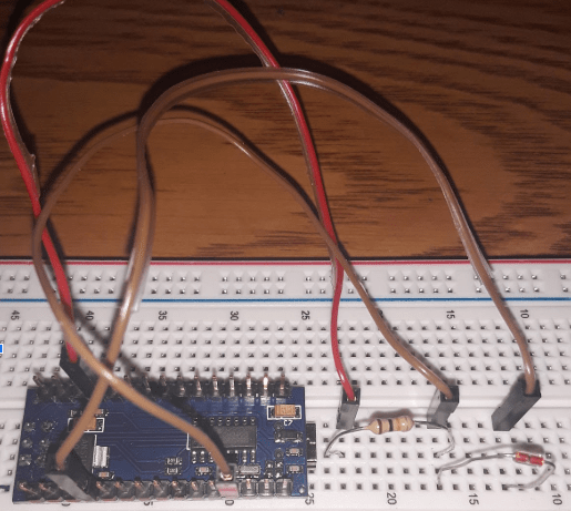
My first milestone was being able to get the wiring and the code for the buzzer to work so later on when connected to the Ultrasonic sensor and motor, a buzz will initiate to give an audio cue of when an object(s) is detected in front of it. When applied any type of voltage, the piezo crystal built inside of the buzzer, pushes up against the diaphragm and creates pressure that then creates a wave that human ears can detect. Once the code is uploaded to the Arduino Via USB code, connect the piezo buzzer the device using jumper wires and an Ohm Resistor. The buzzer must have its positive side on the positive side of the breadbox where you must connect a jumper wire to the same row and connect it to pin 9 on the Arduino. The negative side of the buzzer in that same row connect a jumper wire to pin GND (ground) to ground your circuit, Insert one end of the Ohm resistor to the positive and one to the negative.
Program Used For Coding

const int buzzer = 9; //buzzer to arduino pin 9
void setup(){
pinMode(buzzer, OUTPUT); // Set buzzer – pin 9 as an output
}
void loop(){
tone(buzzer, 1000); // Send 1KHz sound signal…
delay(1000); // …for 1 sec
noTone(buzzer); // Stop sound…
delay(1000); // …for 1sec
}
Wiring For The Buzzer

Schematics For The Sensor

UltraSonic Sensor

// Define pins for ultrasonic and buzzer
int const trigPin = 11;
int const echoPin = 12;
int const buzzPin = 9;
void setup()
{
pinMode(trigPin, OUTPUT); // trig pin will have pulses output
pinMode(echoPin, INPUT); // echo pin should be input to get pulse width
pinMode(buzzPin, OUTPUT); // buzz pin is output to control buzz
}
void loop()
{
// Duration will be the input pulse width and distance will be the distance to the obstacle in centimeters
int duration, distance;
// Output pulse with 1ms width on trigPin
digitalWrite(trigPin, HIGH);
delay(1);
digitalWrite(trigPin, LOW);
// Measure the pulse input in echo pin
duration = pulseIn(echoPin, HIGH);
// Distance is half the duration divided by 29.1
distance = (duration/2) / 29.1;
// if distance less than 0.5 meter and more than 0 (0 or less means over range)
if (distance <= 50 && distance >= 0) {
// Buzz
digitalWrite(buzzPin, HIGH);
} else {
// Don’t buzz
digitalWrite(buzzPin, LOW);
}
delay(60);
}
The UltraSonic Sensor is a gadget designed to emit a frequency through one of its speakers, in which that frequency is reflected back once it hits an object/item and enters through the other speaker.This enables the sensor to determine the distance of the item/object and the time it took for the frequency to come back based on the location of the object. It works exactly how bats use echolocation, the sensor is basically a mechanical bat!
Connect a jumper wire, one end to the GND of the arduino to the row where the GND is located for the sensor in order to ground the circuit. Then connect the ECHO to Pin12 so that the echo is received back once reflected back. Trig and Pin 11 should be connected so that the sound pulses from the sensor are triggered be released. And finally connect the Vcc to the 5v to power the sensor. Once the code is uploaded check the serial monitor to see if any distances are being recorded (they should be numbers).
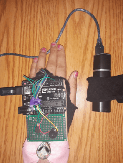
Second Milestone
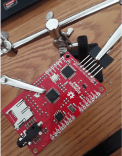
My second milestone was connecting the sensor, motor, and buzzer on one breadboard together and figuring out the wiring for each all while still using one arduino. Then I was able to compile my sketches of coding for each component into one sketch to activate all the key elements at the same time. Finally, now that I have the wiring and code done I can move on to transferring the wires to a perfboard and soldering them on so its more permanent and unlikely to disconnect from its placement. I as well began to sew the sleeve for the charger since the arduino will no longer be connected to a computer and the glove for the sensor.
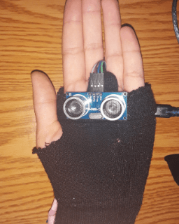
Sensor Glove Piece

Sleeve Piece

Sleeve Piece Pt.2

Third Milestone
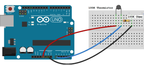
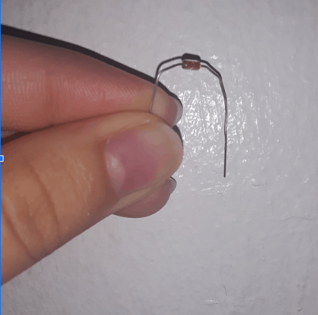
My third milestone was getting the Third Eye to work and detect objects.The sensor both beeps and buzzes due to the piezo buzzer and tiny motor, which I soldiered onto a perfboard. My next goal is to now work on modifications towards my device.My idea for a modification is install various thermistor into the palm,back of the hand,and towards the fingers. A thermistor is both a cold and heat recording sensor that can determine the temperature of the air round it in both fahrenheit or celsius (While coding you can pick either option). This modification would help in aiding the user in avoiding extremely hot and cold temperatures.
int ThermistorPin = 0;
int Vo;
float R1 = 10000;
float logR2, R2, T;
float c1 = 1.009249522e-03, c2 = 2.378405444e-04, c3 = 2.019202697e-07;
void setup()
{
Serial.begin(9600);
}
void loop() {
Vo = analogRead(ThermistorPin);
R2 = R1 * (1023.0 / (float)Vo – 1.0);
logR2 = log(R2);
T = (1.0 / (c1 + c2*logR2 + c3*logR2*logR2*logR2));
T = T – 273.15;
T = (T * 9.0)/ 5.0 + 32.0;
Serial.print(“Temperature: “);
Serial.print(T);
Serial.println(” F”);
delay(500);
}
Thermistor And Individual Wiring
Fourth Milestone
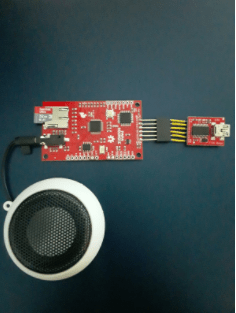
My fourth milestone will be creating a modification in which I add the thermistors in various places on my glove. Using an audio playback device called a “Papa Soundie” so that an audio file that says “hot” and “cold” is played once one of the thermistor sensors detects a temperature nearby that is below 50 degrees fahrenheit and above 90 degrees farenheit. The audio playback device has many of the same pins and processor of an arduino, hence why I will be able to connect the thermistors to my arduino and just connect one of the sensors wires to the Papa Soundie so it leaves the hardware as simple as possible. Using an SD card and a SD card adaptor, I will upload my audio file once I converted it to a Wav. file unto the Papa Soundie.
Audio Play Back Device (PapaSoundie)
Fifth Milestone
My fifth milestone was presenting my device and what I had finished so far which was the base project and also explaining my struggles, learned lessons, and next plans for modifications and when I leave BlueStamp to pursue my career of being a biomedical engineer. Overall my time at BlueStamp was definitely exciting but also really tough since I had never built anything on my own. What really helped me was that the teachers and community here are super supportive they helped me to continue and push through whenever I had issues with my project. I learned to push myself to my limit and never give up and to always try things with a positive outlook regardless of mistakes and failures. After the program I still want to try and work on new projects and practice coding because it’s something I learned to love and its a very beneficial skill to me if I want too become an engineer.