Reflection
For my intensive project at BlueStamp, I decided to make the Tabletop Wanderer Robot based on this Instructable. In the process of making this project, I learned a lot about different hardware and software aspects of robotics. I used to think that building a robot was very difficult and required some genius sorcery. However, by challenging myself to build one of my own, I’ve seen that it is possible to break up the building process into parts and create a great final product.
I’ve also narrowed down the different engineering fields I’m interested in. I’ve enjoyed the mechanical and software aspects of my project, but the electrical part proved to be extremely fickle to troubleshoot, as we couldn’t always be sure if my infrared (IR) issues arose from bad hardware, problems with my circuitry, or something else. As of right now, if I can find a form of engineering that combines math and physics with software, I would be very interested in it.
BOM (Bill of Materials): this is the list of all the materials I used to create my final product
Build Plan: this is my initial plan for building this robot. I switched the order of the first and second milestones, programming my Arduino with the infrared sensors first, and then building my chassis.
Code: a repository of the final code for my robot can be found here.
Schematic: the final schematic of my robot is here.
A presentation and demo of my robot can be seen below.
Milestone #3: Completed Robot
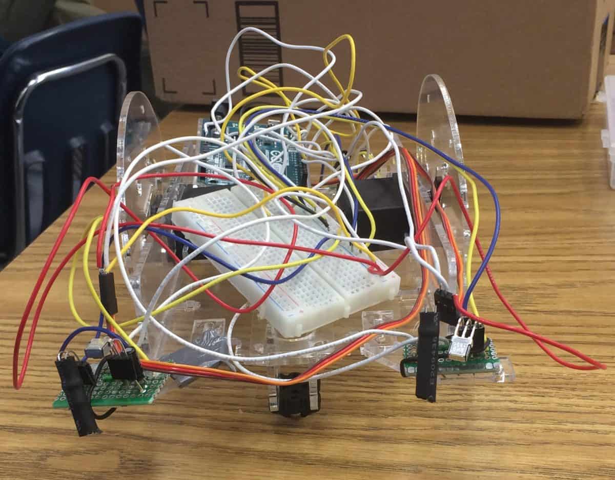
For this milestone, I finished my Tabletop Wanderer Robot. I assembled my chassis, mounted my infrared (IR) sensors onto the robot, and got my robot to the sensors.
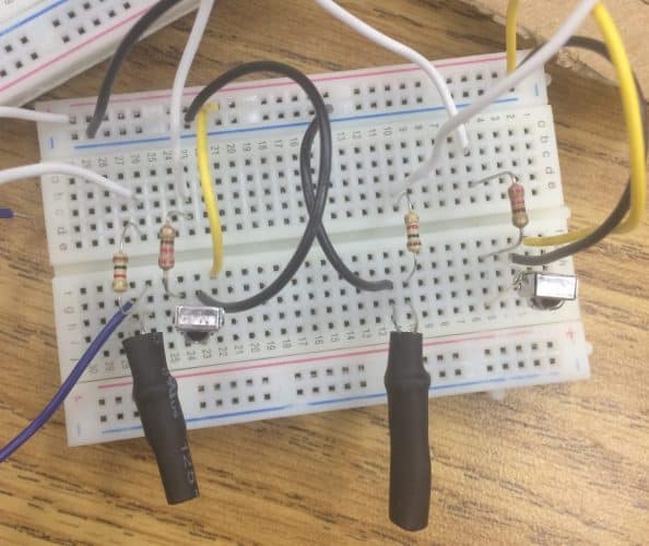
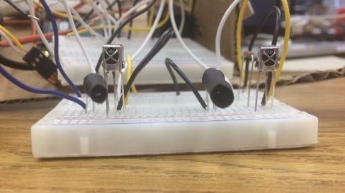
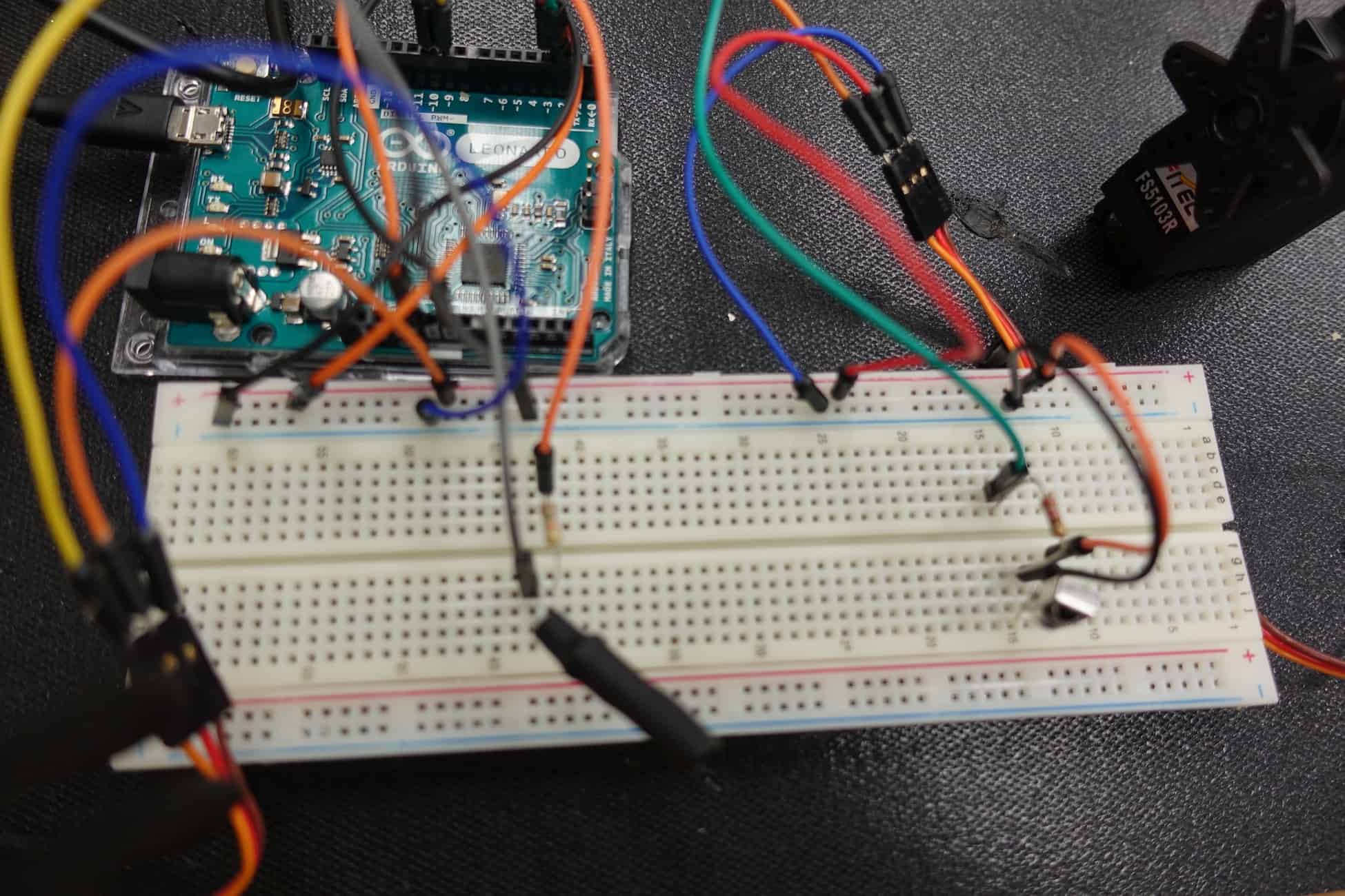
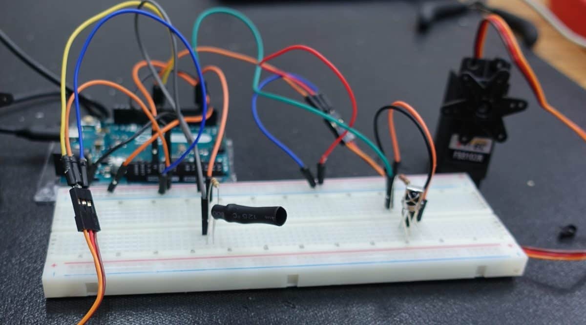
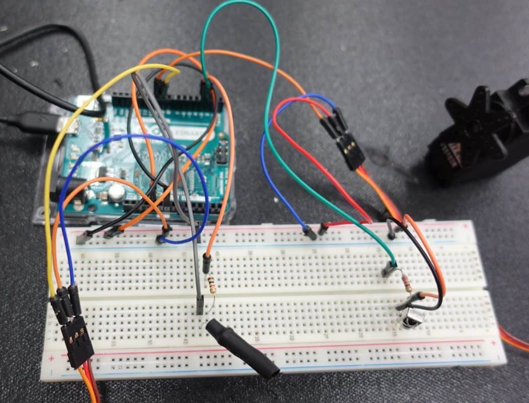
As in milestone 2, I had huge issues with IR in this milestone, and spent another week troubleshooting. I initially put my IR sensors in a breadboard, a small board that can be used to prototype components and circuits. When I tested these IR sensors after milestone 2, they didn’t work. I tried many combinations, checked my wiring, and nothing seemed to work. I then did some research and found out that the IR detectors could require a low-pass filter (a combination of capacitors and resistors that can filter out IR waves from the environment) in order for there to be a solid detection. I used some 22 uF capacitors in parallel with the detector and the resistor I had in previously in order to create the filter, and the sensors started working. However, I had even more issues with IR.
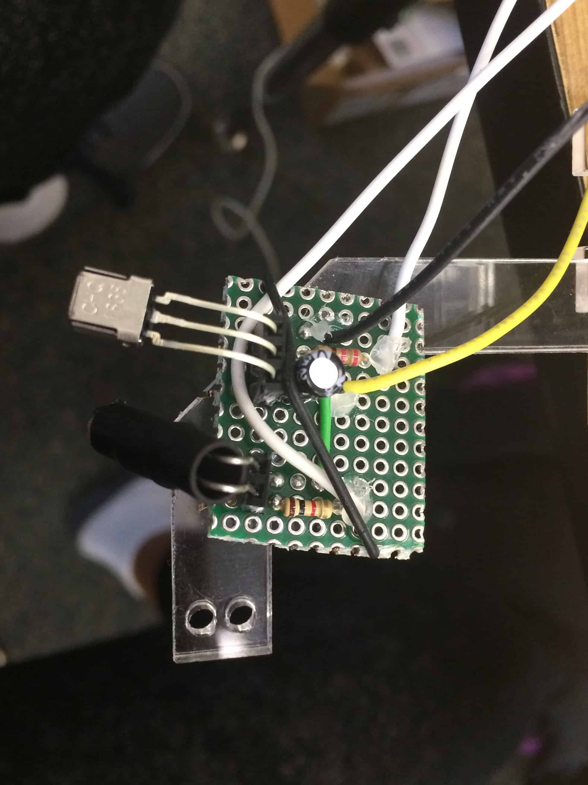
My next challenge was moving the IR sensors from the breadboards to PCBs (Printed Circuit Boards that allow one to create an actual circuit) and soldering the sensors in. This proved to be very difficult for several reasons.
The first issue was creating common ground between the emitter and detector. I realized that the ground levels between the two components could be different (i.e. one at 1 V and the other at 2 V). The instructors told me this would cause issues when I ran power through the circuit. To solve this issue, I initially created solder bridges between the negative terminals of each component. The solder bridges consisted of melted wire that connected one component the other. This method didn’t work, as the solder didn’t conduct the electricity well enough for the common ground to work. Eventually, I started using jumper wires to connect the negative terminals, and connecting these wires to the ground provided by the Arduino. This solution worked, so I kept it in my PCB.
I also had huge issues when soldering in the actual emitters and detectors into the boards. I found that the emitters/detectors worked in the breadboards, but when I moved them to the circuit board, they stopped working. The detectors would consistently read in only 0s (surface detected), or only 1s (surface not detected). I tested many circuits with multimeters and other devices, but I couldn’t find anything wrong.
After several troubleshooting attempts, I finally cut the legs of the emitters/detectors I had soldered in the PCB board and putting these components back in the breadboards to test them. I tried several combinations, testing emitters from the breadboard with the detector from the PCB board, and the detector from the breadboard with the emitter from the PCB board. Through these trials, I realized that the detectors of the PCB boards didn’t work after I soldered them in. I was told that this was likely because I was soldering the detectors at higher temperatures than what they could handle, burning the circuitry in them.
To fix the high temperature issue, I tried heat-sinking the emitters and detectors by using alligator clips to absorb the heat from the iron while soldering the components in. I tested the circuit board, and it still didn’t work.
Finally, I tried soldering in pin connector headers into the circuit. These allowed me to allocate a space for the sensors without having to expose them to the heat of the soldering iron. I could put the emitter/detector in the headers once the PCB board had cooled down after soldering. This method proved to be effective, and I finally got a sensor module that worked.
However, I still had to recreate this module three more times. I had issues with the “copies” of the modules, as even though the emitters/detectors worked, sometimes my solder bridges wouldn’t conduct electricity well enough for current to reach the component. Other times, even the instructors couldn’t identify the problem with the circuit, at which point I had to dump the board and try again.
Overall, I went through over 10 attempted circuits, of which I got 5 to work (I created an extra module just in case one the four modules I was using for my robot malfunctioned). I was able to connect these to a common breadboard with my servos and control them well with my Arduino.
Getting the chassis was a problem in and of itself. UPS and the U.S. Postal Office consistently lost my package, or stated that it hadn’t been delivered. They once delivered the package, but took it back because they weren’t able to obtain a signature. This resulted in a delay of about 5 days in getting the chassis.
Once I got the chassis, I found that the screws and other hardware we had at the classroom weren’t the right size/model as the ones needed to put the chassis together. I decided to just use superglue to enhance the friction-fit that the laser cut parts had come with. In this part of the milestone, I also learned how to use a Dremel (a power tool that can cut, drill, and perform other functions on surfaces) to enlarge some of the holes for my servos because they wouldn’t fit in the holes in the laser-cut parts.
Once the chassis was assembled, I was able to mount the circuits onto the arms of the chassis, and connect them to the servos and Arduino. I had to adjust the angle of the IR emitters/detectors so they were perfectly aligned to detect IR. I found that if I cut the heat shrink wrap on the IR emitter down, the span of the IR emitted increased, so the detector could detect IR from farther away, and the angles of the sensors didn’t have to be as precise.
Now that this milestone has been completed, I’d like to get my IR to be more precise so the robot consistently doesn’t fall off the table (right now, the IR is still shaky, and the instructors say that it’s probably just the hardware). I’d like to modify the robot so it has a sensor to detect objects in front of/behind the robot. If there’s enough time, I’d like to try making remote control capabilities for the robot, so you can dictate where it goes.
A Github repository of my code for this milestone can be found here.
A schematic of my circuits can be found here.
Cardboard Prototype and Sensors
Milestone #2: Cardboard Prototype
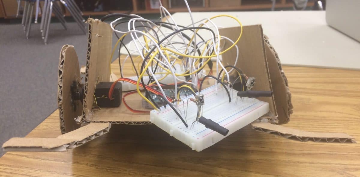
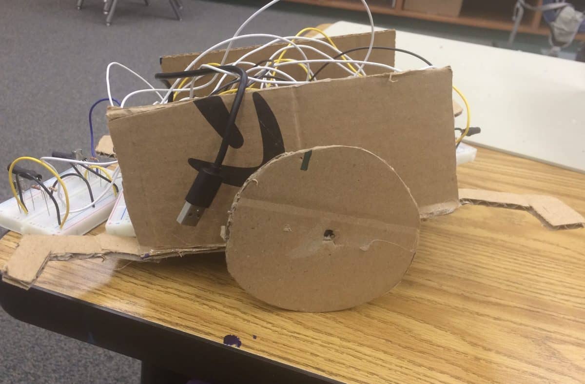
For this milestone, I made a cardboard prototype of my robot that responded to the surfaces detected by the 4 infrared (IR) sensors I put in breadboards.
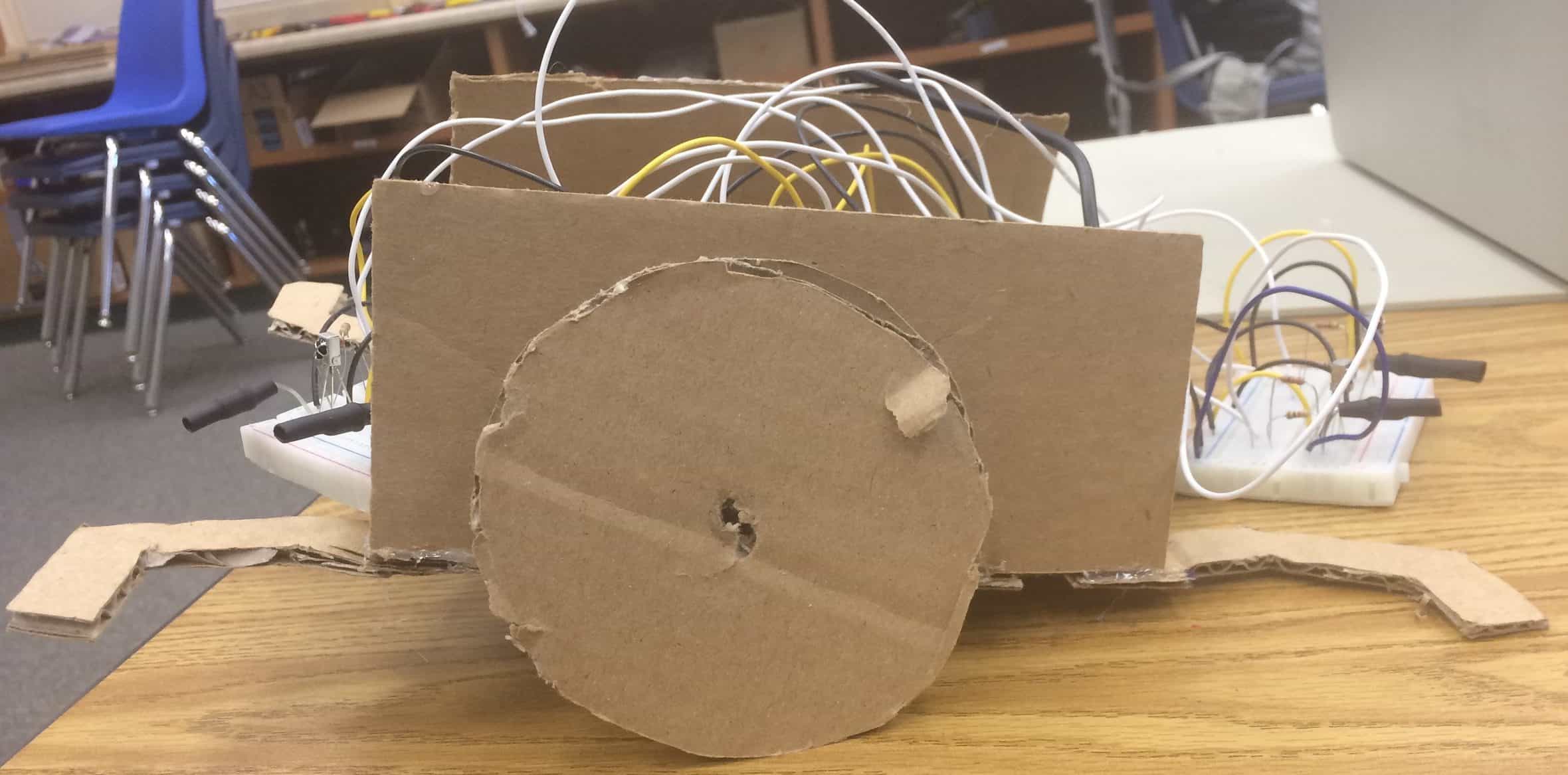
I decided to design and make the cardboard chassis because the Instructables website I was using for guidance didn’t have dimensions for the laser cutter files it provided for the chassis. I measured and cut out the cardboard pieces of the chassis using an X-acto knife. Cutting with the knife was slightly difficult, and I had some issues getting my measurements right. In the end, I designed the base and walls of the chassis, and added four arms to hold my IR sensors. I also designed wheels to attach to my servos (motors that can turn continuously and can be used to make a wheel).
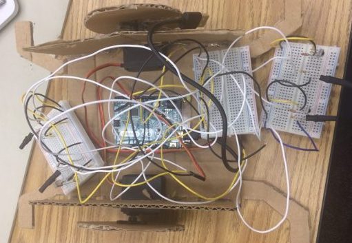
I cut out places for my servos to fit through the walls of the chassis, and fastened the servos in with paper fasteners. I did the same thing with my Arduino, placing it at the center of the base of my chassis. Then I started my breadboard circuits with my IR emitter-detector pairs.
I had IR issues in this milestone, as well. Each emitter-detector pair worked fine on its own, but when I tried to use two at once, one wouldn’t work. I replaced the emitters with regular LEDs, and found out that one would blink at a rate of 38 kHz, but the other emitted a steady light. It took some troubleshooting, but I figured out that this was because I was trying to call the tone() method of Arduino, the function I was using to create a 38 kHz tone, on two different pins, when in reality you can only call it on one pin (unless you use the noTone() method).
To fix this issue, I decided to use a “main” breadboard that would connect to all of my components (all the sensors and the servos), and provide them direct power from the Arduino. I put two emitter-detector pairs on two different breadboards (for a total of four pairs), and connected one pin from the Arduino to the main breadboard. I then connected each emitter from the two side breadboards to the main breadboard, essentially connecting them to one pin. I also connected my servos to the main breadboard, and provided power for each of these components.
Finally, when I tested the robot, it worked, and I was able to see my wheels rotate and move my chassis whenever a surface was detected by all four sensors.
Code for this milestone can be found here. A schematic of my breadboards can be found here.
For my next milestone, I want to assemble my acrylic plastic chassis and solder in all my components in actual circuit boards. I will then mount this circuit on the chassis, and complete my robot.
Cardboard Prototype and Sensors
Milestone #1: Breadboard Circuit
The project I am making at BlueStamp is a TableTop Wanderer Robot. It can wander around a table on its own without falling off.
My first milestone involved getting my IR (infrared) detector to detect surfaces, and having my servo motors respond to the detection. If a surface was found, the servos would rotate clockwise. If a surface was not detected, the servos would stop. This is because when a surface is not detected, it means the robot is near the edge of the table and shouldn’t move any farther.
I had huge problems with my IR detectors and emitters, and I spent about a week troubleshooting all the issues. My first detector-emitter pair actually contained an IR emitter and a two-pin IR detector. At first, my IR emitter would not emit IR waves. I learned that I could use the selfie camera of my iPhone to see the IR light from the emitter, and I couldn’t see any light initially. To fix this problem, I tried replacing the IR emitter with a regular LED (light-emitting diode) to see if it would light up. When it did, I knew that current was flowing across that part of the circuit. I then put my emitter and detector back into the circuit, and used the analogRead() function of my Arduino to determine if the detector was detecting any IR waves. I found data printing just fine, but after some research I realized that ambient IR waves, or IR found in the environment, could affect my readings, causing my detector to detect environment waves as opposed to my emitter’s. I then coded my Arduino to subtract the IR detected when my emitter was off (ambient IR) from the IR detected when my emitter was on (emitted IR). The result was 0, meaning nothing had been detected.
I tried a new approach, sending a 38 kHz signal to my detector by using the tone() method provided by Arduino. I had done some research and found out that some detectors require a signal between 37-39 kHz to differentiate between ambient IR, IR that is “floating” around in the environment, and emitted IR. However, when I pointed my emitter at a surface, I got what can only be described as a “wild” range of values: from -315to over 286. I was told this was likely background “noise” from ambient IR waves that I would have to filter out.
I tried putting the emitter closer to the detector, then farther, and neither of these attempts changed the readings. I tried putting heat shrink wrap (a wrapping that can “shrink” to fit snugly on a component when heat is applied to it) on my IR detector, then on my emitter, and then on both, in order to focus the IR that was being sent and received. The result was a constant 0 reading, which meant that nothing was being read, regardless of whether a surface was present or not.
Finally, I was advised to use a three-pin detector as opposed to a two-pin one. I did a lot of research to figure out how to use this detector, and realized that I could use the digital readings of 0 (IR wave detected) and 1 (IR wave not detected) to determine if a surface was present or not. At first, my emitter detected “too much,” detecting IR waves through paper and cardboard. Later on, I tried heat shrink wrapping my emitter, which improved my readings slightly, but still caused somewhat random readings of 0 and 1. After some research, I found that keeping a resistor in series with the IR detector and emitter can “reduce” the sensitivity of the emitter/detector pair, filtering out background noise and focusing on what the IR emitter is sending. After putting the resistors in series with each component, and re-wrapping my emitter with more heat shrink wrap, I finally got the detector to detect the surfaces accurately.
Once I got my IR sensors working right, it was a simple process of getting my servos hooked up and having them respond to the surface detection as needed. I wrote values between 0-180 to the servos, where 0 moves the servo in one direction, 90 stops the servo, and 180 turns the servo in the other direction.
A GitHub repository of my code for this milestone can be found here.
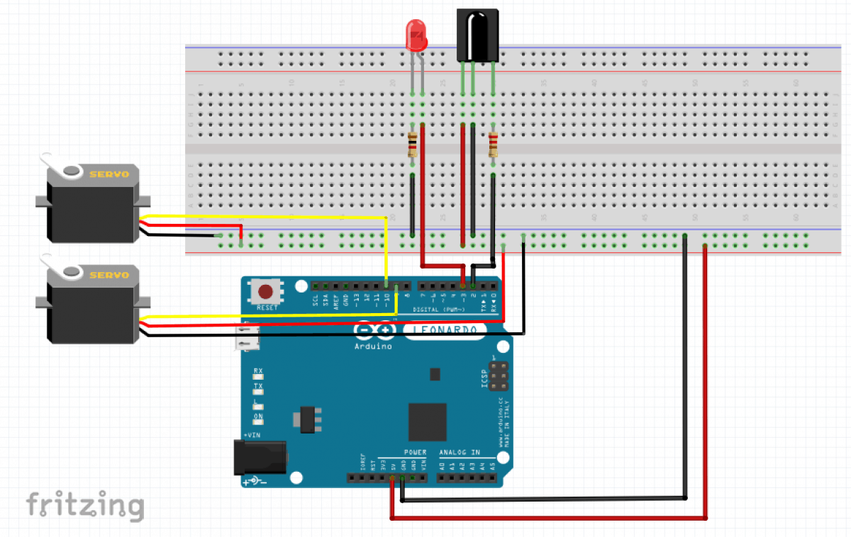
A schematic of my breadboard circuit can be found here.
For my next milestone, I want to put my circuit into an actual circuitboard, and build the chassis for my robot.
Breadboard Circuit
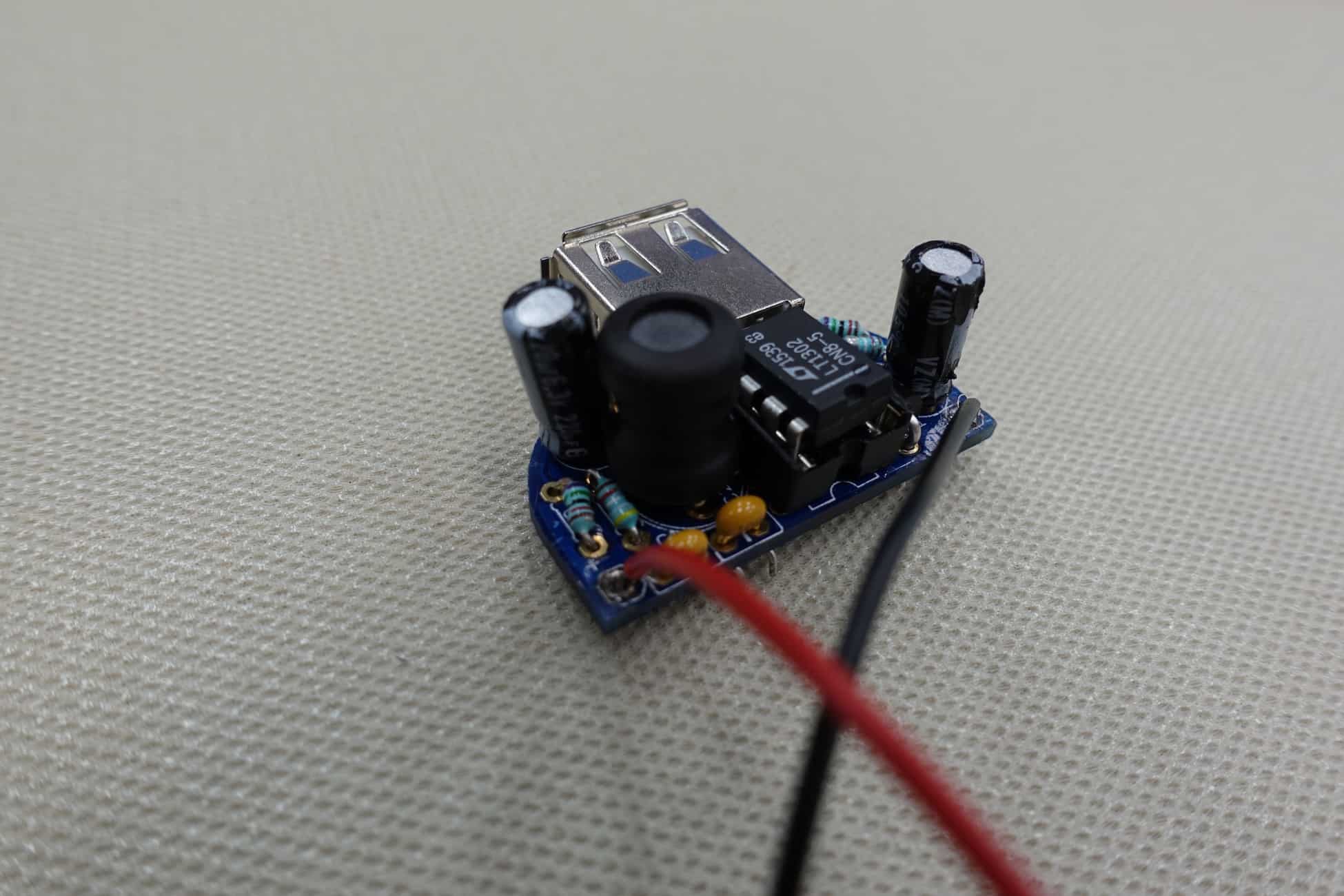
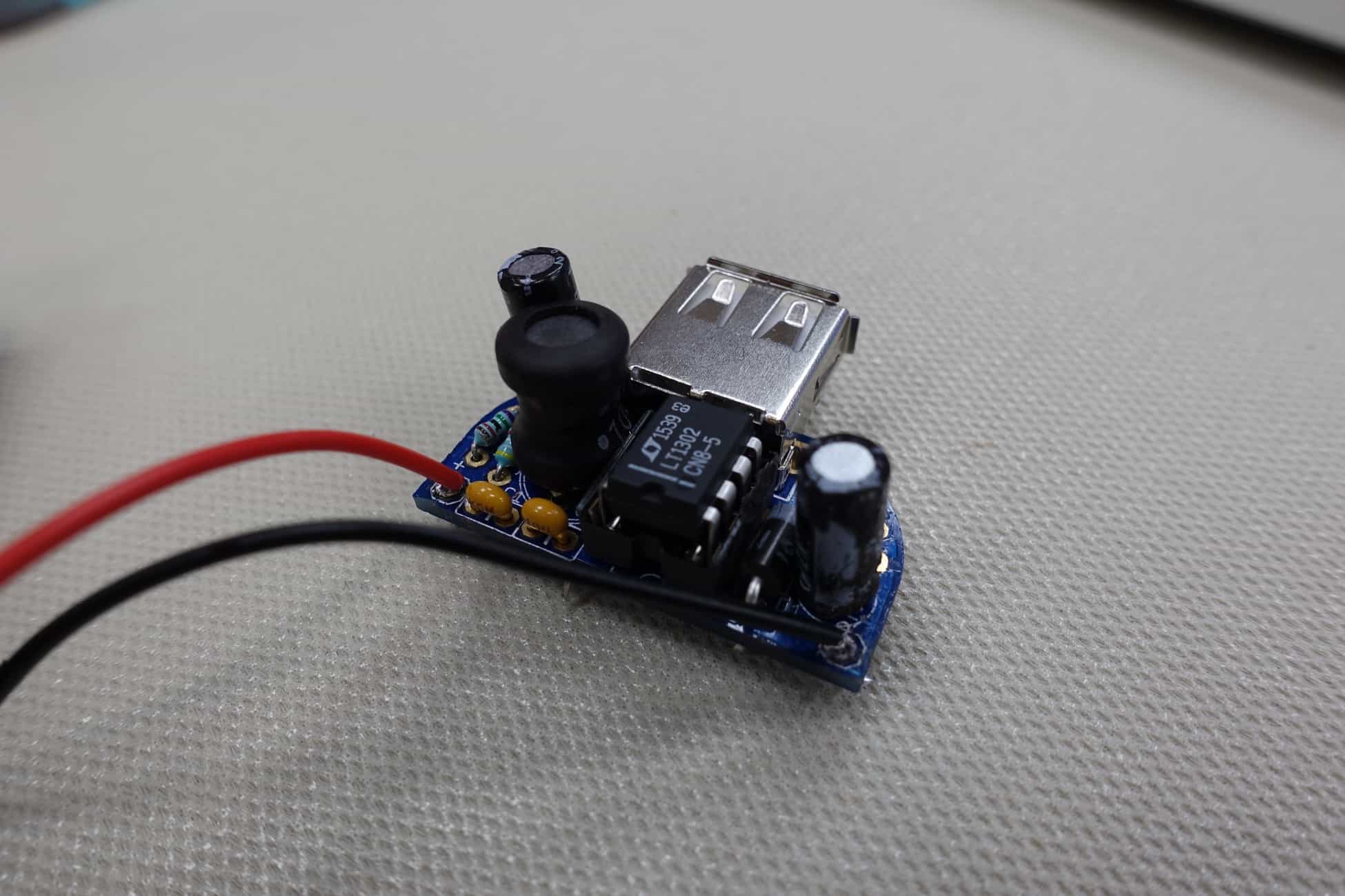
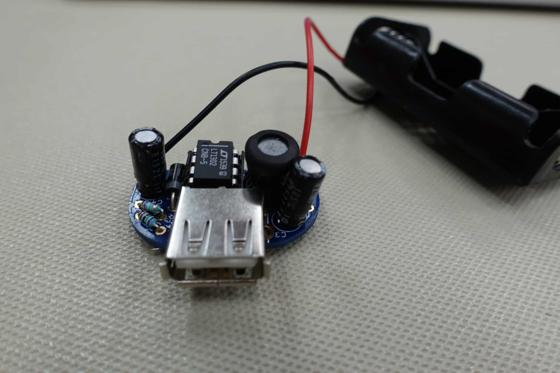
Starter Project: MintyBoost Phone Charger
My starter project was the MintyBoost portable phone charger. The charger came as a kit from Adafruit, which I assembled and soldered with the help of the instructions from the Adafruit website. I faced several problems with this project, most of which involved desoldering parts that had been put in the circuit board incorrectly and re-soldering them the correct way. I also had to spend a lot of time researching each component and its purpose in the circuit.
The kit came with several resistors, which served to control the amount of current coming from the battery. I initially soldered in one of the resistors a little carelessly, thinking that as long as current would flow through it, it wouldn’t matter. However, I later realized that the IC socket would have to go over this resistor, and the soldered in resistor hindered the IC socket. This was the first time I had to desolder in my project, and it took almost an entire day to get the resistor out. Soldering a replacement resistor in was another issue, as the circuit board holes where the old resistor was were full of solder. I used a screw and the soldering iron the remove the solder from the hole and put the new resistor in.
The kit also had a polarized diode, which served to control the direction of the current. I initially soldered in the diode the wrong way, which caused the boost converter chip to heat up very quickly. I had to desolder and replace diode, an extremely time-consuming process. In the process, I broke the wires from my battery pack. This meant I had to desolder the parts of the wire that were stuck in the circuit board, remove the solder from the circuit holes with a screw, re-strip the wires, and solder them into the holes again.
The kit also came with capacitors, which serve to store electric potential energy across the plates. There were two kinds of capacitors: electrolytic and ceramic. The electrolytic capacitors contained one plate made of electrolyte, which oxidized the opposite metal plate of the capacitor, creating a dielectric between the plates. This capacitor was polarized, and, having learned from my diode mistake, I was especially careful to solder it into the circuit board the correct way. The ceramic capacitors, on the other hand, utilized a ceramic dielectric and were not polar. This meant I could solder them in the circuit board without having to regard their direction.
I also soldered in an IC Socket, which served to protect the boost converter chip from heat from soldering. The chip itself increased the voltage provided by the battery from 3 V to 5V. It did this through the use of an inductor, which contained one coil. This coil resisted changes in current, so it resisted the current that initially flowed through it when the circuit was fully connected. To resist the current, the coil induced a current of its own, creating a magnetic field. This field helped increase the voltage from the battery to create a voltage that was actually useful for the device to be charged.
The final components I soldered in were the USB port and the battery pack. The USB port allowed a pathway for power to travel from the circuit board to the charging device, and proved to be fairly easy to solder. I faced more difficulty with the battery pack, as the wires often broke, and I had to desolder the wires, re-strip them, and solder them in again on four different occasions.
Overall, creating the project took about 3 days, and I learned a lot more about circuits and the components going into them. I have definitely gained a new respect for electrical engineers and the process of creating circuits.


