TrackMe GPS Tracker
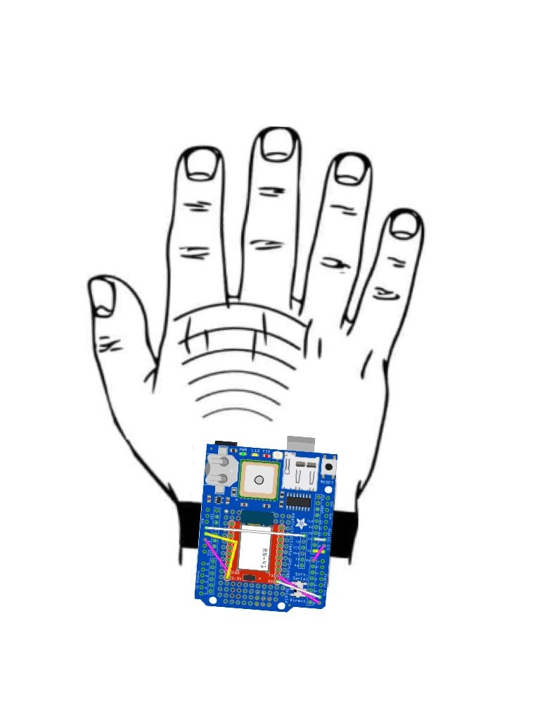
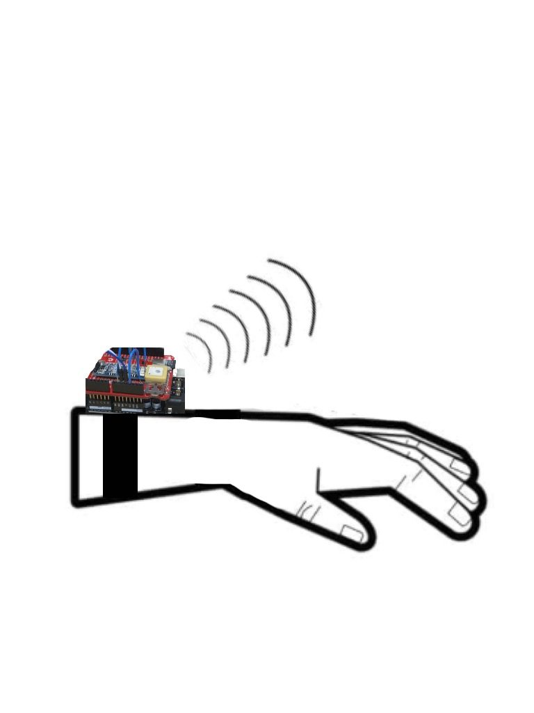
TrackMe is a portable and wearable GPS Tracker. The device uses an Arduino, a GPS Module, and an HM-10 Bluetooth Module to record and transmit user location data over the course of a day via a custom-built iOS Application.
Engineer
Anisha B.
Area of Interest
Computer Science
School
Fremont High
12th grade
Incoming Senior
Reflection
All my code, documentation, schematics, and planning is available on my Github and Build of Materials. View my presentation video below!
Final Milestone
TrackMe is a portable and wearable GPS Tracker. The device uses an Arduino, a GPS Module, and a HM-10 Bluetooth Module to record and transmit user location data to a Serial Monitor, log data onto an SD Card, or transmit data via the TrackMe App, an IOS Application built specifically for the Tracker.
The Arduino uses the TinyGPS++ library to record user data. TinyGPS++ parses NMEA data streams provided by GPS modules and can extract arbitrary data from any of the myriad NMEA sentences available.
The TrackMe IOS Application relies on two frameworks: Mapkit JS and Core Bluetooth. Mapkit JS creates a map displaying user location and the user’s exact coordinates. Core Bluetooth, more importantly, creates a serial that allows communication between the User and the Arduino through a HM-10 Bluetooth Module.
Lastly, the Arduino uses both Hardware and Software Ports in order to keep the tracker functional. A SoftwareSerial Port is used to relay information from the GPS to the Arduino, and a Hardware Port (HW-UART) is used to relay information from the Arduino to the Bluetooth Module.
GPS Features + Statistics
The GPS Tracker records
- longitude
- latitude
- altitude
- speed
- date (DD/MM/YY)
- time (GMT)
- SD Card Logging
- Navigational Direction
Accuracy and Statistics
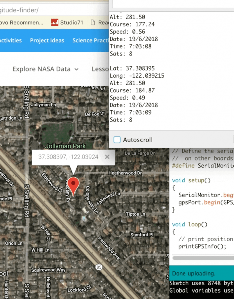
Measurements recorded by the GPS are accurate up to 4 decimal points. The tracker takes 30-60 seconds to establish a fix when placed outdoors. When placed indoors, the Tracker may take up to 5 minutes to find a fix.
Arduino Libraries + Quick Links
TrackMe App Features + Statistics
TrackMe consists of
- About Page
- Contact Page
- Map View
- Bluetooth Serial
Additional information about each of the page’s features can be found on the page below.
Frameworks Used
- Core Bluetooth Framework
- provides the classes needed to communicate with devices that are equipped with Bluetooth low energy wireless technology.
- Mapkit JS Framework
- The JavaScript API for embedding Apple maps on your website.
Accuracy and Statistics
The application can communicate with the Tracker from a distance of up to 100 meters.
ABOUT TRACKME
The TrackMe IOS App consists of 4 new features: About, Contact, Features, and Map Pages. The About Page provides the User with an introduction to the Tracker itself and the Tracker’s compatibility with external devices via Bluetooth. The Contact Page contains a hyperlink to this BlueStamp Website and an additional hyperlink that opens up an email draft directly in Gmail, with the recipient and the subject specified. The Features Page lists all the GPS’s features and what exactly the device records when powered up. The Page additionally lists all the different possible outlets to transmit information to. Lastly, the Map Page displays a rendering of the user’s current location.
FRAMEWORKS USED
The IOS Application utilizes the built-in Mapkit JS Framework, the JavaScript API for embedding Apple maps onto applications. This framework was used to create a map of the user’s current location and a pinpoint was added to mark the user’s exact coordinates. Additionally, the app uses the Core Bluetooth Framework, which provides the classes needed for TrackMe to communicate with the Tracker using Bluetooth low energy wireless technology. The Framework was used to create a “serial” to enable communication to and fro both devices.
Third Milestone
Bluetooth Attachment
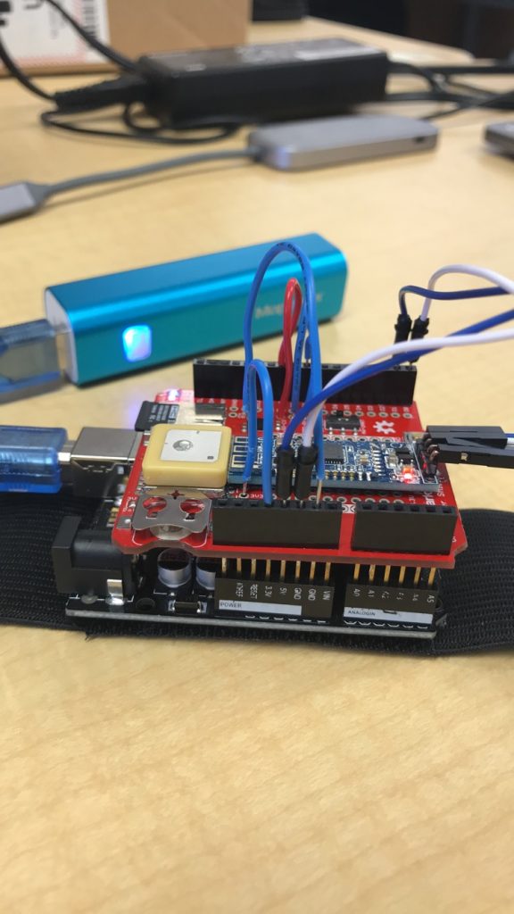
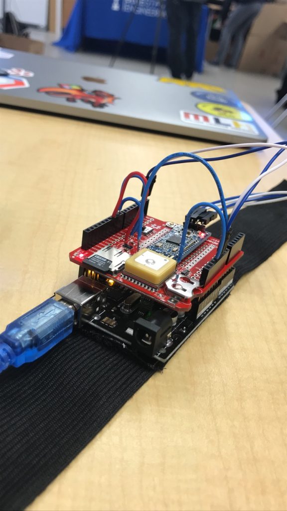
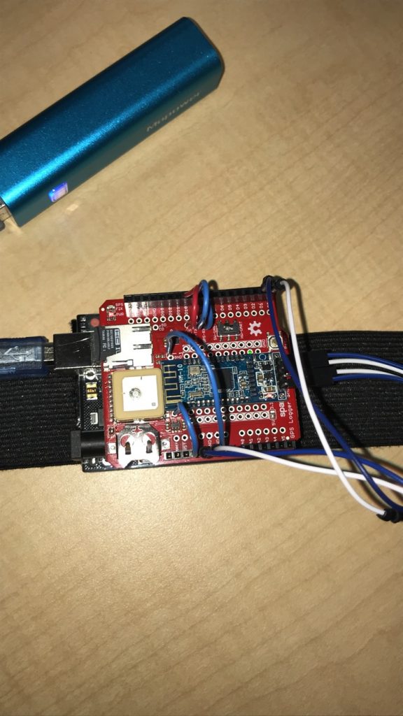
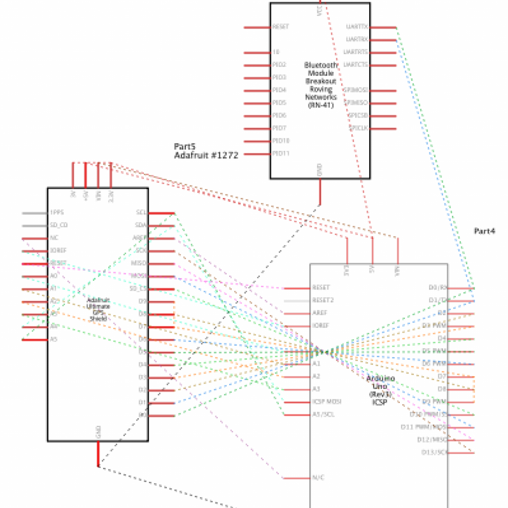
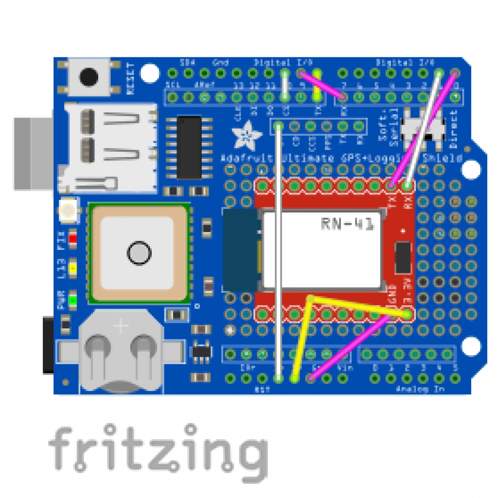
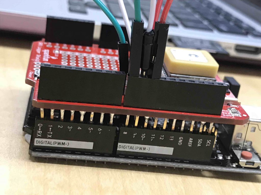
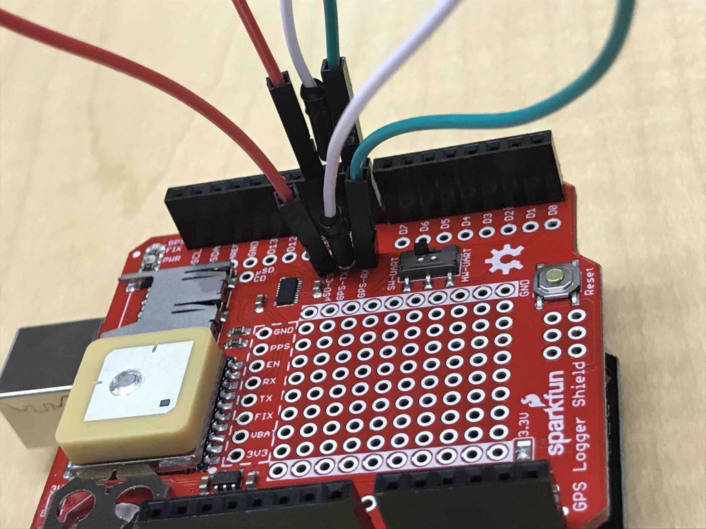
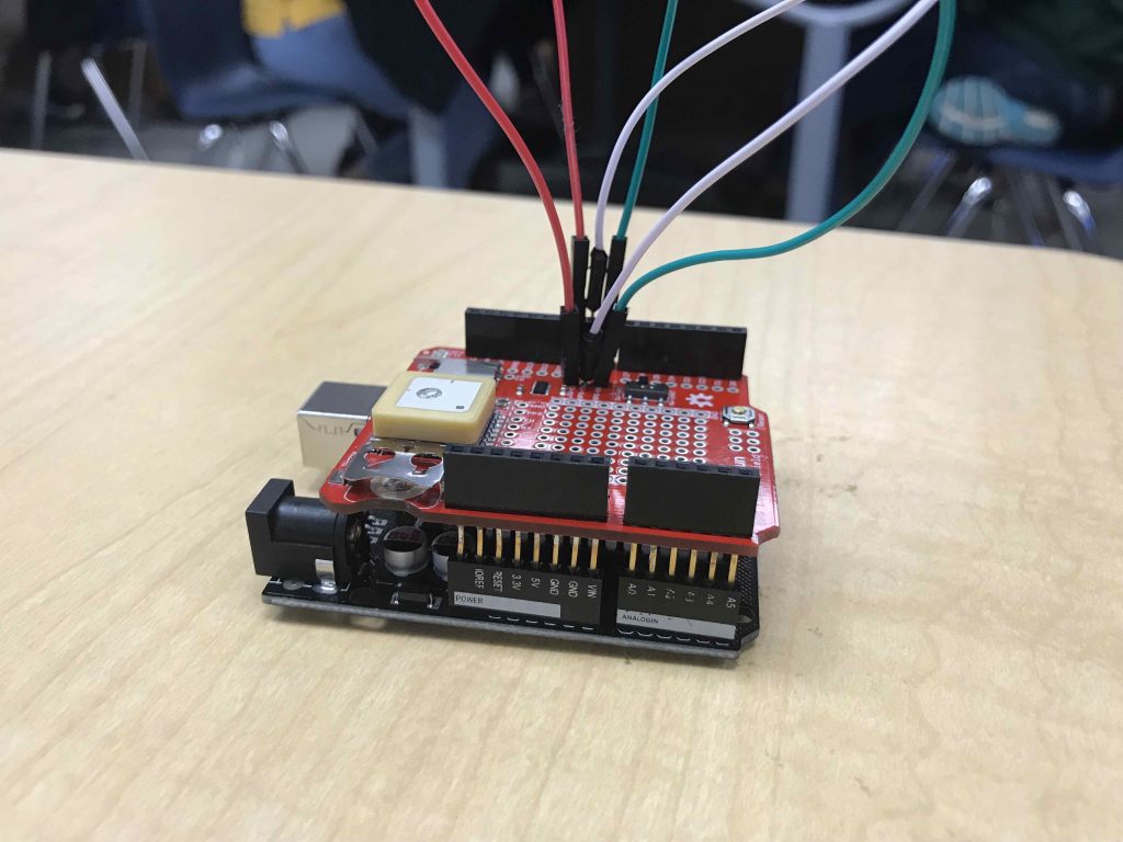
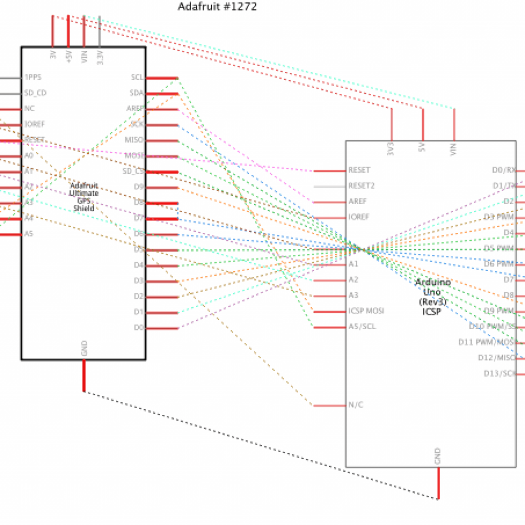
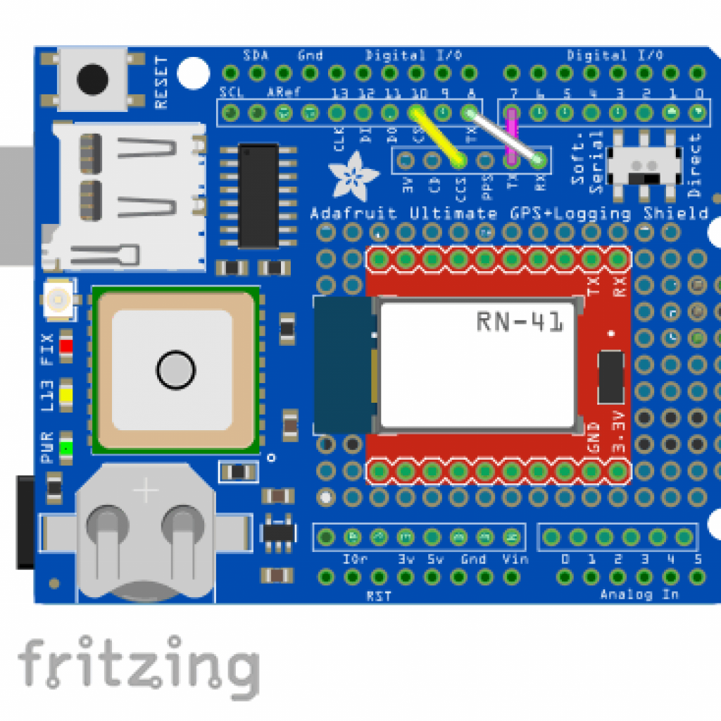
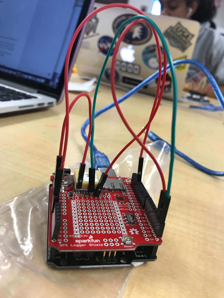
A HM-10 Bluetooth Module was attached to the Shield in order to enable Serial Communication. The Module has 4 pins: RX (receive), TX (transmit), 5V, and VCC, all of which were connected to the Shield. More specifically, the TX and RX pins were connected to the ShieLD’S Hardware Ports (Digital pins 0 and 1).
code rewrite
Next, the original GPS code was entirely rewritten to consider user input. Instead of logging all of the information at once, the user can now send commands to retrieve one or multiple pieces of information at one time.
GOALS
For my next milestone, I hope to modify the code for the Bluetooth App to personalize the tracker as more of a service and product.
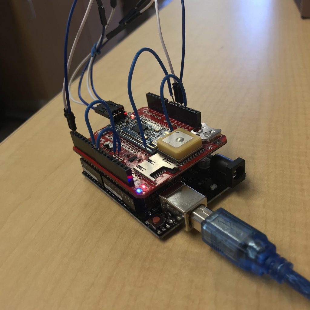
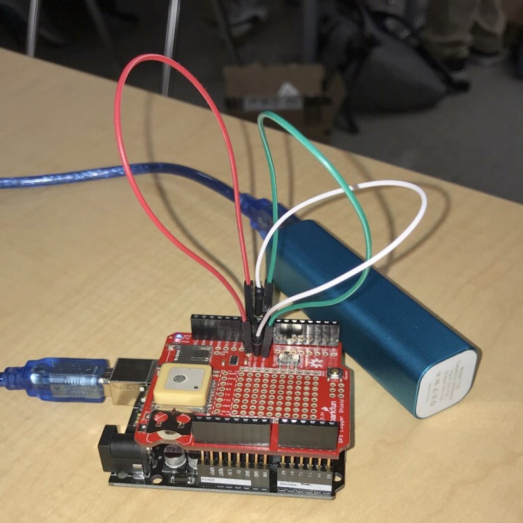
SHIELD + Bluetooth WIRING
I had trouble with the wiring of the shield to match the flow of information coming back and forth from the GPS, Arduino, and the Bluetooth Module. I solved this problem by troubleshooting and checking each aspect of my project for functionality: I attempted creating multiple SoftwareSerial ports for the Bluetooth module and the GPS. However, in the end, I realized that the module would only send commands to the Arduino when connected to the hardware port (Digital Pins 0 and 1), and that the GPS information would only display when connected to a Software Serial Port (Digital pins 8 and 9). This wiring works because the module sends and receives data from the Arduino. The Arduino then sends the commands to the Software Serial Port, which receives GPS data that is sent to the module, eventually appearing on the phone.
Second Milestone
code rewrite
Next, the code for the program had to be changed in order to create files in the SD Card and transport the information from the GPS Directly into the SD Card. The new GPS information is logged into a brand new CSV file on the SD Card, with 8 columns detailing current longitude, latitude, speed, altitude, date, time, course, as well as the amount of satellites that the GPS is currently connected to.
First Modification
For my first modification, I altered the code to make it adaptable to google fusion tables. As a result, the data from the SD card is now integrated into a satellite map, displaying the entire path taken during a trip. Each recorded location is represented by an icon that displays the user’s current longitude, latitude, speed, altitude, course (in degrees), date, and time. The format of time was changed from milliseconds to standard military time, and the date was changed from DDMMYY to MM/DD/YY to increase readability. The information is also used to generate a heatmap, that represents repeated locations recorded over one specific area during a period of time. Lastly, this same information can be transferred over to Google Earth as well if wanted.
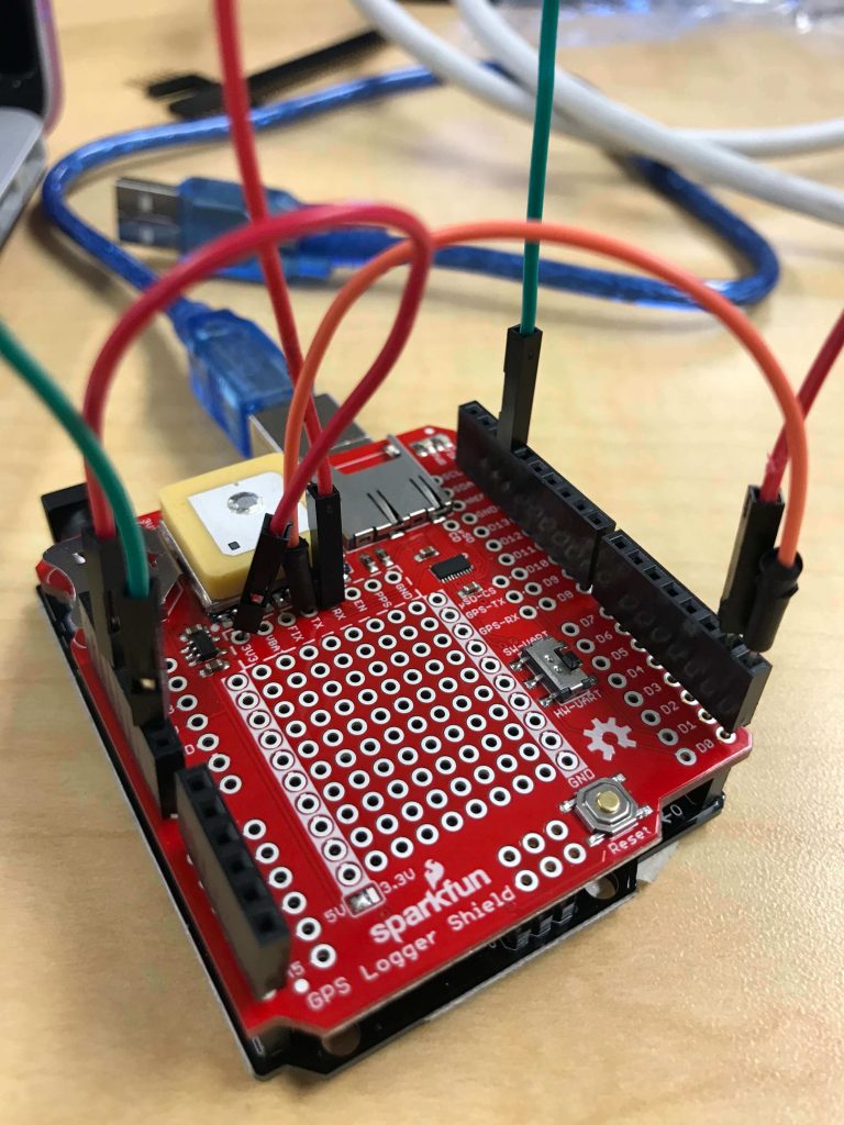
Shield wiring
Delving into the wiring of the Shield, the Shield requires the wiring of three necessary pins: TX, RX, and the CS pin. TX and RX stand for Transmit and Receive, respectively, which are essential for the GPS to receive instructions from the Arduino and to send data to the SD card. The CS pin checks if the card is present and can be initialized, and sends the data to the SD Card. I had trouble with the wiring of the shield to match the flow of information coming back and forth from the GPS, Arduino, and the SD Card. I solved this problem by troubleshooting and checking each aspect of my project: my code, the Arduino, the SD Card, the Shield, and the headers attached to the shield. In the end, I realized that as long as the Arduino and the GPS were connected using the TX and RX pins and Pin 10 was connected to the CS pin, the data from the GPS could be accurately saved.
First Milestone
Features + Statistics
The GPS Tracker records
- longitude
- latitude
- altitude
- speed
- date (MM/DD/YY)
- time (GMT)
Accuracy and Statistics
Measurements recorded by the GPS are accurate up to 4 decimal points. The tracker takes 30-60 seconds to establish a fix when placed outdoors. When placed indoors, the Tracker may take up to 5 minutes to find a fix.
Quick Links + Parts Used
Quick Links
Parts Used
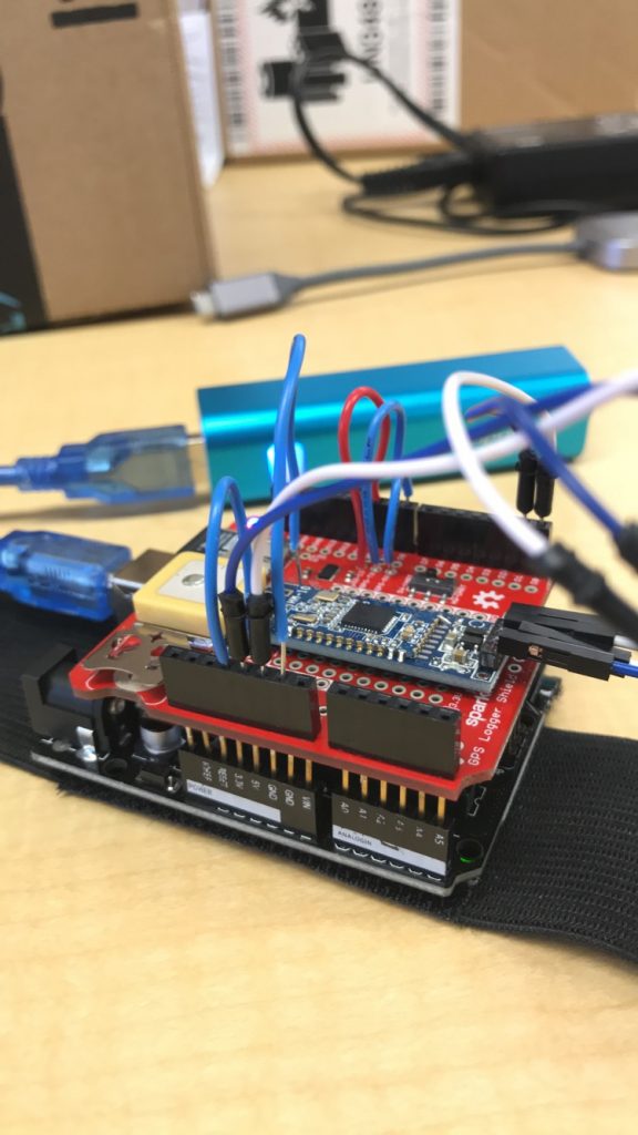
I used an Arduino Elegoo (Uno), and a Sparkfun GPS Logger Shield to collect data, and the TinyGPS++ library for my code.
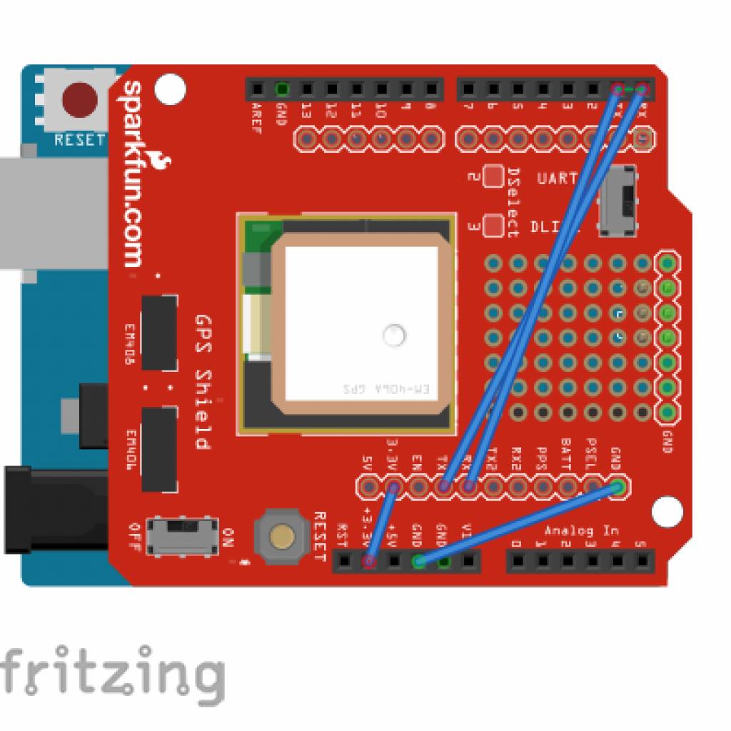
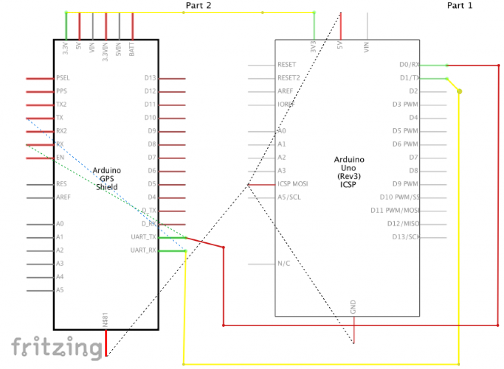
Wiring
I first attached the Arduino and the Shield using headers. However, I later ended up soldering all of the headers onto the logger shield itself to establish a stronger connection. I was fortunate enough to find sample code to work off of (Serial Transmitting Code), but faced the challenge of wiring the proper pins to make them both work together. As I did not have a battery to fit into my shield, I soldered a 3v3 jumper in order to provide enough energy to keep the shield functional. The shield has three jumper cables. The first cable connects the GND pin to the Arduino’s GND. The second jumper cable connects the GPS’s TX pin (transmit) to Pin 9, the Arduino’s RX pin. Finally, the last jumper connects the GPS’s RX (receive) pin to Pin 8, the Arduino’s TX pin. Through this wiring, the Arduino is able to send instructions to the GPS and later receive information from the GPS, which is displayed on the computer.
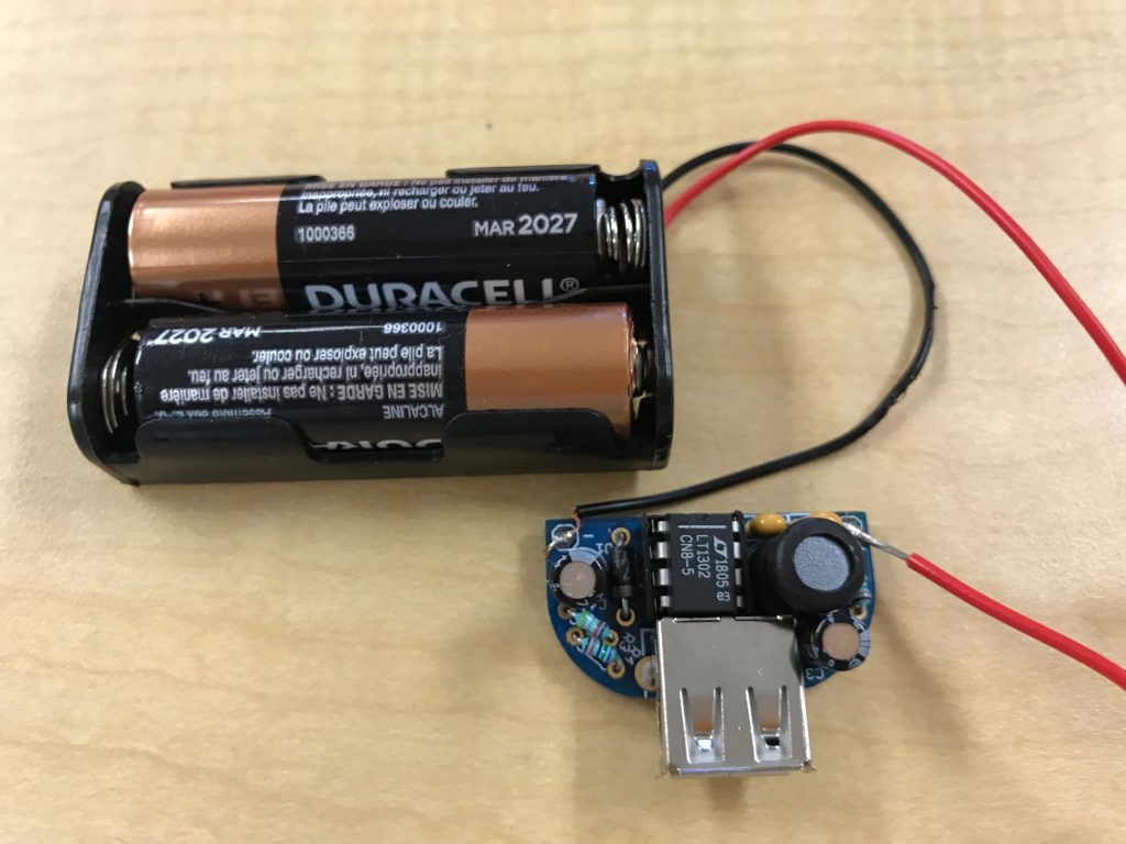
Starter Project
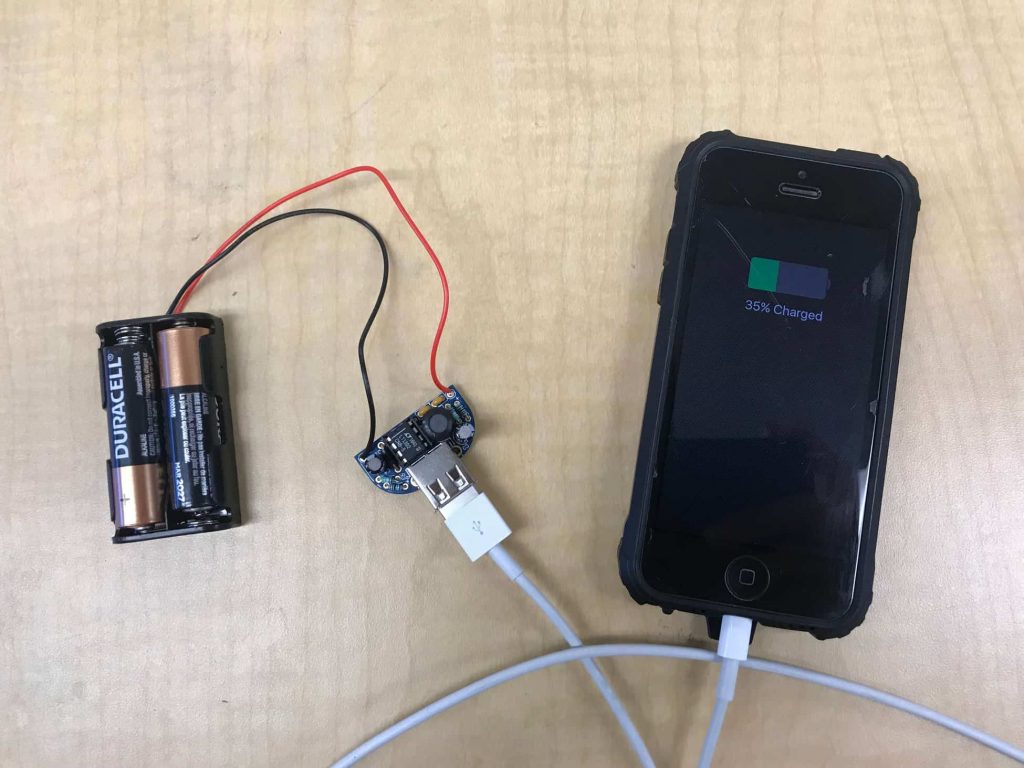
CAPABILITIES
Charges:
- Iphones, Androids
- Cameras
- MP3 Players
Requires:
- 2 AA Batteries
- USB Cable
Images can be clicked for enlargement.
Connectivity
Charger