Hand Gestured Controlled Car
The hand gestured controlled car contains two parts, the glove and the car. The Glove includes four flex sensors. The different combinations of the flex sensors will determine which motors will move. This will make it seem like the car is controlled by my hands.
Engineer
Angus F.
Area of Interest
Engineering
School
Bard High School Early College
Grade
Incoming Junior
Reflection
Working on this project, I learned a lot about engineering and myself. I learned three different aspects to engineering which were electrical, software and mechanical engineering. I learned a lot about these three types of engineering because there was no clear documentation on how to build my project so I had to research everything that came with my project and figure out how to combine all the parts into one working project. I spent the first two weeks researching this and experimenting different ways to wire everything but it was also very frustrating because nothing went my way. But through these six weeks, I learned to persevere through hard times and also to research everything I have and Google is a very good friend.
Final Milestone
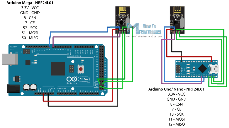
I finished my final milestone and my project, the Hand Gestured controlled car. It includes two parts, the NRF communication and the car chassis. Basically the flex sensors are sewed to a glove and connected to an Arduino Nano where the NRF transmitter is also wired to. The Nano will read the change in resistance and send the variables over to the NRF receiver connected to the Arduino Uno where the servo and DC motors are connected to.(Figure 1). The Arduino Uno will then use the variables and determine which action to take.
How it works
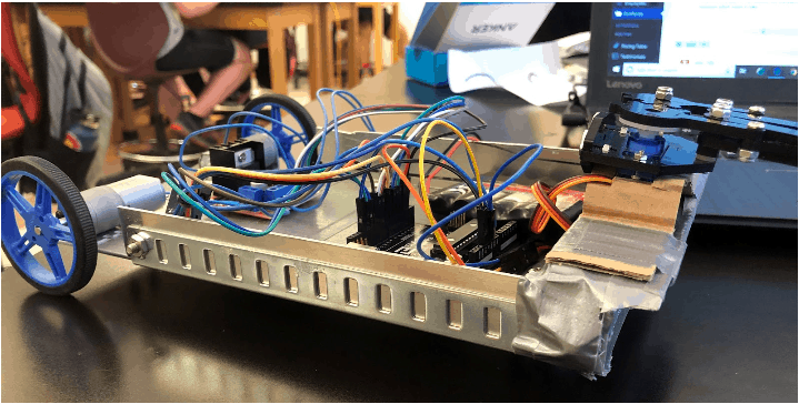
The NRF24L01 is a wireless receiver and transmitter and the transmitter sends over code and data to the receiver which then reads it and operates on the data sent over. They operate in the frequency of 2.4 GHz. In my code, the flex sensors have their own variables, so four in total. The NRF transmitter, connected to the Nano, will send the different variables of the flex sensors over to the NRF receiver which is connected to the Arduino Uno. Since the servos and the DC motors are also connected to the Uno, the Uno will receive which flex sensors are bent through the NRF communication. The Arduino Uno will then decide what to do with the servos and DC motors. The car chassis contains many parts all cut out from a huge aluminum sheet and connected using brackets. Duct tape was used to wrap around the chassis to prevent the Arduino Uno and the motor driver to short.
#include <SPI.h>
#include <nRF24L01.h>
#include <RF24.h>
int sensorvalue1 =0;
int sensorvalue2 =0;
const int EnA = 10;
const int EnB = 5;
const int In1 = 9;
const int In2 = 8;
const int In3 = 7;
const int In4 = 6;
const int flexpin1 = A0;
const int flexpin2 = A1;
const int flexpin3 = A2;
const int flexpin4 = A3;
const int num = 4; // Declare array size
int Array[num];
bool b1 = 0;
bool b2 = 0;
bool b3 = 0;
bool b4 = 0;
char motion[] = {b1, b2, b3, b4};
RF24 radio(7, 8); // CE, CSN
const byte address[6] = “00001”;
void setup() {
Serial.begin(9600);
radio.begin();
radio.setChannel(80);
radio.openWritingPipe(address);
radio.setPALevel(RF24_PA_MIN);
radio.stopListening();
}
void loop() {
Array[0] = analogRead(flexpin1); //sets the flex sensors into arrays
Array[1] = analogRead(flexpin2);
Array[2] = analogRead(flexpin3);
Array[3] = analogRead(flexpin4);
Serial.println(Array[0]); Serial.println(Array[1]); Serial.println(Array[2]); Serial.println(Array[3]);
radio.write(&Array, sizeof(Array));
}
#include <SPI.h>

#include <nRF24L01.h>

#include <RF24.h>

#include <Servo.h>

Servo servo1;

Servo servo2;

unsigned long lastChange = 0;

int sensorvalue1 = 0;

int sensorvalue2 = 0;

const int EnA = 10;

const int EnB = 2;

const int In1 = 9;

const int In2 = 6;

const int In3 = 5;

const int In4 = 4;

const int flexpin1 = A0;

const int flexpin2 = A1;

const int flexpin3 = A2;

const int flexpin4 = A3;

const int num = 4;  // Declare array size

int Array[num];

int sensor1 = 0;

int sensor2 = 0;

int sensor3 = 0;

int sensor4 = 0;

bool b1 = 0;

bool b2 = 0;

bool b3 = 0;

bool b4 = 0;

bool isopen = 0;

char motion[] = {b1, b2, b3, b4};

RF24 radio(7, 8); // CE, CSN

const byte address[6] = "00001";

void setup() {

  Serial.begin(9600);

  radio.begin();

  radio.setChannel(80);

  radio.openReadingPipe(0, address);

  radio.setPALevel(RF24_PA_MIN);

  radio.startListening();

  Serial.begin(9600);

  // All motor control pins are outputs

  pinMode(EnA, OUTPUT);

  pinMode(In1, OUTPUT);

  pinMode(In2, OUTPUT);

  pinMode(flexpin3, INPUT);


  pinMode(EnB, OUTPUT);

  pinMode(In3, OUTPUT);

  pinMode(In4, OUTPUT);

  pinMode(flexpin4, INPUT);

  pinMode(3, OUTPUT); // PWM output to servo 1

  servo1.attach(3);// telling where signal pin of servo1 attached(must be a PWM pin)

  servo1.write(180);

  /*

    Serial.print("OPENING SERVO");

    servo1.write(90);

    delay(2000);

    Serial.print("CLOSING CLAW");

    servo1.write(180);

  */

}

void Stop() {

  digitalWrite(EnA, LOW);  //motors dont move

  digitalWrite(EnB, LOW);

}

void Forward() {

  digitalWrite(EnA, HIGH);  //motors move forward

  digitalWrite(EnB, HIGH);

  digitalWrite(In1, HIGH);

  digitalWrite(In2, LOW);

  digitalWrite(In3, HIGH);

  digitalWrite(In4, LOW);

}

void Backward() {

  digitalWrite(EnA, HIGH);   //motors move backwards

  digitalWrite(EnB, HIGH);

  digitalWrite(In1, LOW);

  digitalWrite(In2, HIGH);

  digitalWrite(In3, LOW);

  digitalWrite(In4, HIGH);

}

void Left() {

  digitalWrite(EnA, HIGH);   //motors move left

  digitalWrite(EnB, HIGH);

  digitalWrite(In1, HIGH);

  digitalWrite(In2, LOW);

  digitalWrite(In3, LOW);

  digitalWrite(In4, HIGH);

}

void Right() {

  digitalWrite(EnA, HIGH);   //motors move right

  digitalWrite(EnB, HIGH);

  digitalWrite(In1, LOW);

  digitalWrite(In2, HIGH);

  digitalWrite(In3, HIGH);

  digitalWrite(In4, LOW);

}


void loop() {

  // exit: delay(1);

  if (radio.available()) {         //checks is radio is available

    radio.read(&Array, sizeof(Array));     //finds the size of array from the transmitter

    sensor1 = Array[0];

    sensor2 = Array[1];

    sensor3 = Array[2];

    sensor4 = Array[3];


    Serial.print(b1); Serial.print(b2); Serial.print(b3); Serial.println(b4);


    if (sensor1 > 450) {

      b1 = 0 ;

    }

    else if (sensor1 <= 451) {

      b1 = 1;

    }

    if (sensor2 > 450) {

      b2 = 0 ;

    }

    else if (sensor2 <= 451) {

      b2 = 1;

    }

    if (sensor3 > 500) {

      b3 = 1 ;

    }

    else if (sensor3 <= 499) {

      b3 = 0;

    }

    if (sensor4 > 450) {

      b4 = 1 ;

    }

    else if (sensor4 <= 451) {

      b4 = 0;

    }

    if (b1 == 1 && b2 == 1 && b3 == 1 && b4 == 1) {

      Forward();

      Serial.println("Forward");

    }

    if (b1 == 0 && b2 == 0 && b3 == 0 && b4 == 0) {

      Stop();

      Serial.println("Stop");

    }

    if (b1 == 0 && b2 == 0 && b3 == 1 && b4 == 1) {

      Backward();

      Serial.println("Backward");

    }

    if (b1 == 1 && b2 == 1 && b3 == 0 && b4 == 0) {

      Left();

      Serial.println("Left");

    }

    if (b1 == 1 && b2 == 0 && b3 == 0 && b4 == 1) {

      Right();

      Serial.println("Right");

    }

    unsigned long now = millis();

    if (b1 == 1 && b2 == 0 && b3 == 0 && b4 == 0 && (now - lastChange >= 1000)) {

      Serial.println("hi");

      lastChange = millis();

      switch (isopen) {

        case 1: //claw is open

          //action

          Serial.println("is open");

          servo1.write(175);

          isopen = 0;

          //goto exit;

          break;

        case 0: //claw is closed


          servo1.write(90);

          isopen = 1;


          break;

      }


    }

  }
}
Second Milestone
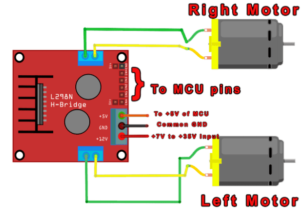
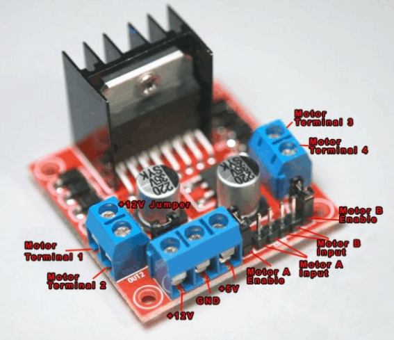
My second milestone for the Hand Gesture Control Robot was to control the DC motors with my flex sensors. Specifically, when the flex sensor is bent and to make the motor stop when the flex sensor is straight. The motors are connected to a motor controller board which is used to control the motors better than connecting the motors straight to the Arduino Nano. The motor controller board is used to control the direction is which the motor spins. Figure 2 shows how the motor driver controller board is connected to the two motors.

How it works
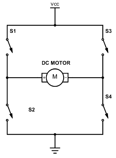
This specific motor controller is a L298N and the motor drive controller has four inputs that are connected to the four inputs in the H-bridge in the L298N. An H-bridge is a circuit that changes the direction of the motor spinning. There are four switches in the H-bridge as shown in figure 3. These switches are what determines the direction in which the motor spins. For example, if S1 and S4 are turned on and S2 and S3 are turned off, the motor will spin to the right. There are two inputs for each motor and a pin to enable each motor (figure 4). These 6 pins are connected to digital pins on the Arduino Nano. Signals will be sent from the Nano to the motor driver, and then to the motor terminals where the motors are connected. After figuring out how to turn the motors by itself, next came the flex sensors. I had to somehow make one motor turn when a flex sensor bends. I took all the code I had for flex sensors, motors and servos and took parts of different codes and combined them into one. Refer to milestone one for more information on how flex sensors work.
const int EnA = 10;
const int EnB = 5;
const int In1 = 9;
const int In2 = 8;
const int In3 = 7;
const int In4 = 6;
const int flexpin3 = A2;
const int flexpin4 = A3;
int sensor1 = 0;
int sensor2 = 0;

void setup()
{
Serial.begin(9600);
// All motor control pins are outputs
pinMode(EnA, OUTPUT);
pinMode(In1, OUTPUT);
pinMode(In2, OUTPUT);
pinMode(flexpin3, INPUT);

pinMode(EnB, OUTPUT);
pinMode(In3, OUTPUT);
pinMode(In4, OUTPUT);
pinMode(flexpin4, INPUT);
}

void loop()
{
sensor1 = analogRead(flexpin3);
if(sensor1>450){
Serial.println("Motor on");
Serial.println(sensor1);

// turn on motor A
digitalWrite(In1, HIGH);
digitalWrite(In2, LOW);
// set speed to 150 out 255
analogWrite(EnA, 255);
}
else if(sensor1<451){
digitalWrite(In1, LOW);
digitalWrite(In2, LOW);
}

sensor2 = analogRead(flexpin4);
if(sensor2>450){
Serial.println("Motor on");
Serial.println(sensor2);

// turn on motor A
digitalWrite(In3, HIGH);
digitalWrite(In4, LOW);
// set speed to 150 out 255
analogWrite(EnB, 255);
}
else if(sensor2<451){
digitalWrite(In3, LOW);
digitalWrite(In4, LOW);
}

}
This can be seen in the code:
digitalWrite(In1, HIGH); //this makes motor one turn forward

digitalWrite(In2, LOW);

digitalWrite(In3, HIGH); //motor two turn backward

digitalWrite(In4, LOW);
This tells the Arduino Nano to turn on switches 1 and 3 and this will make both motors move in one direction.
First Milestone
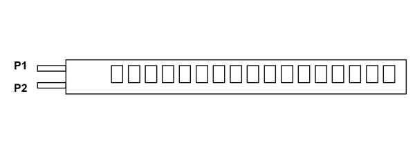
My first milestone for the Hand Gesture Control Car was to connect the servos to the Arduino Nano and to get the servos to react from the bending of the flex sensors. Flex sensors are variable resistors where the resistance of the flex sensor increases as it is bent. The straighter the flex sensor is, the lower the resistance. The flex sensor has two pins (figure 2). P1 is usually connected to the power source and P2 is connected to ground.
Figure 1: See milestone 1 if Hand Gesture Control Robot
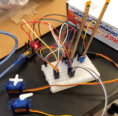
Figure 2: Two pins on the flex sensor, P1 for power source and P2 for ground
How it works
My first milestone includes a flex sensor, a resistor for a voltage divider, servos and an Arduino Nano. The flex sensor changes resistance due to how linear it is. Resistance increases the more it gets bent. A resistor/ voltage divider is basically there to detect the change in resistance. Add voltage divider picture and explanation There is a base resistor and the flex sensor is the resistance that changes. The micro servo is a gear motor and contain three wires. One for ground, one for power and one for the digital input. Micro servo starts moving after all three wires are connected to the Arduino Nano and the flex sensor is bent. The Arduino Nano is basically a smaller version of the Arduino Uno. The Nano has the same function as the Uno but does not contain the same number of pins. So when the flex sensor is bent, the servo will move and when the sensor is straight, the servo returns back to its original position.
// Include the servo library to add servo-control functions:

#include <Servo.h>

// Create a servo "object", called servo1. Each servo object

// controls one servo (you can have a maximum of 12):

Servo servo1;

Servo servo2;

// Define the analog input pin to measure flex sensor position:

const int flexpin1 = A0;

const int flexpin2 = A1;


void setup()

{

// Use the serial monitor window to help debug our sketch:

pinMode(5, OUTPUT);

//Serial.begin(9600)

pinMode(flexpin2, INPUT);

servo1.attach(5);


// Use the serial monitor window to help debug our sketch:

pinMode(9, OUTPUT);

Serial.begin(9600);

pinMode(flexpin1, INPUT);

// Enable control of a servo on pin 9:

servo2.attach(9);

}

void loop()

{

int flexposition1 = analogRead(flexpin1);


int flexposition2 = analogRead(flexpin2);

int servoposition1 = map(flexposition1, 4, 13, 0, 540);

servoposition1 = constrain(servoposition1, 0, 540 );


int servoposition2 = map(flexposition2, 4, 13, 0, 540);

servoposition2 = constrain(servoposition2, 0, 540 );

servo1.write(servoposition1);

servo2.write(servoposition2);

Serial.print("sensor: ");

Serial.print(flexposition1);

Serial.print("  servo: ");

Serial.print(servoposition1);

Serial.print("    sensor2: ");

Serial.print(flexposition2);

Serial.print("  servo2: ");

Serial.println(servoposition2);

delay(20);  // wait 20ms between servo updates

}
There were many parts to the code. For example, there had to be a code to include two servos instead of one and it had to include the two flex sensors. The code is:
Servo servo1;

Servo servo2;

// Define the analog input pin to measure flex sensor position:

const int flexpin1 = A0;

const int flexpin2 = A1;

This is telling the Arduino Nano that there are two servos and the two flex pins, one connected to A0 and one connected to A1, each control one servo. A0 and A1 are analog pins that the flex sensors are connected to and it measures the position of the flex sensor.
Starter Project
My starter project is the motion alarm from Sparkfun https://learn.sparkfun.com/tutorials/sparkfun-inventors-kit-experiment-guide—v40/circuit-3c-motion-alarm. This project uses light, motion and sound to either scare or alert others when it comes within 10 inches of the motion sensor. It can be used as many things from an alarm that scares your cat away or it can also act as a room alarm.
How it works
There is a motion sensor in the form of distance. If it senses an object within 10 inches or less, the light changes from green to red, the servo starts moving, and the piezo buzzer starts making noise. The motion sensor is ultrasonic. It works like echolocation. There are two parts: 1) a transmitter, the part that sends out the waves and, 2) a receiver, the part that receives the waves after it bounces off an object. See figure 1 for a diagram of how the distance sensor works. A servo is a motor with three wires sticking out of it. One is for power, one is for ground and one is for control inputs. A piezo buzzer is a vibrator that makes a loud noise. After we put everything on the breadboard, all that is left is to add the code to the Arduino Uno R3. An Arduino Uno R3 is a microcontroller. In a microcontroller, we can input code for sensing a controller a digital system. The code basically tells the Arduino that once the ultrasonic sensor receives something, the light changes from green to blue, the piezo buzzer starts vibrating and the servo starts moving.
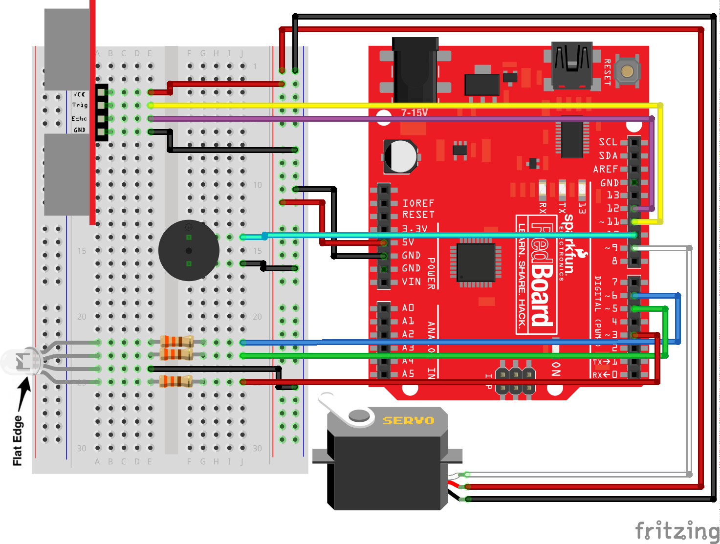
Figure 1: how a Ultrasonic Sensor works

Figure 2: The Motion Alarm


