Introduction
Hi! My name is Andrew and I am a rising Senior at the Urban School of San Francisco. I first heard about BlueStamp through a presentation at my school’s Tech Team. I knew I liked science and math, and had some experience building circuits from my physics class. I decided to apply to BlueStamp because I wanted to continue to explore my interests and their practical applications.
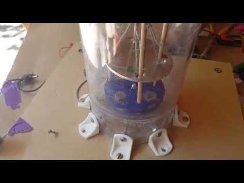
Magnetic Levitation Final Project
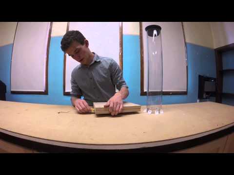
For my main project my goal was to levitate an aluminum disc using the opposing magnetic field generated by a changing magnetic field. Here is the final video for my project, in which I was actually able to levitate the aluminum disc. Initially the disc is unable to float because the motor isn’t spinning fast enough, but it begins floating at 3:00
Here is another video of the project that I took a few weeks after BlueStamp had ended. In this video I used a lighter aluminum disc so that the levitation is more visible. However, because the disc is much lighter, the friction from the wooden dowels makes it sit unevenly above the magnets.
To create this changing magnetic field I spun a disc of alternating magnets at around 10,000 rpm using a 3D-printed magnet holder and a small brushless motor. Here is my Bill of Materials. Aluminum is not ferromagnetic, but does conduct electricity, so the changing magnetic field induces an electric current in the aluminum, which in turn generates an opposing magnetic field, as dictated by Lenz’s Law. Here is a good explanation of Lenz’s Law.
Here is a demonstration of how I applied Lenz’s Law in my project.
Magnet Holder Design Process
When I was figuring out what I could use to hold the magnets as they spun, my two main concerns were weight and durability. I chose to 3D print my design using Polylactic Acid (PLA) because it is very lightweight and often used in mechanical applications. I chose to 3D model and print my design so that I could continue to update it as I tested each design.

Here is the the link to the first design that I printed.
In this design I had planned to use twelve magnets in a Halbach Array, as can be seen below.

A Halbach Array from Wikipedia
When spun, the Halbach Array is supposed to be more power efficient than the North-South array that I ended up using. The major flaw with this design was that using twelve magnets in addition to the large magnet holder made it too heavy for my motor to handle. I tried to address that issue in my next design.

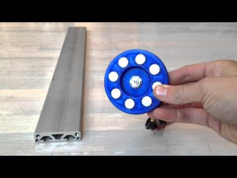
Here is the link to the second design that I printed
When I was modeling my second, and current, design, I knew I needed to cut out a lot of weight from my first design, so I decided to use only four magnets, alternating North-South. My hope is that the increased motor speed will make up for having less magnets spinning, and it will be able to generate enough force to levitate an aluminum disc
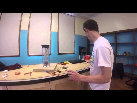
Magnetic Levitation- Milestone #2
For my second milestone I put together the safety framework for my project. I built a base board that I can attach the motor to so that it can be clamped down, and attached the tube where I will try to levitate the aluminum disc. I have a magnet holder and aluminum disc that I can test with, and while the generated force visibly affects the aluminum, as of right now I can’t generate enough force to overcome the force of gravity on the aluminum disc. As I move forward in my project I plan to redesign and reprint my magnet holder and order a lighter weight aluminum disc.
Magnetic Levitation- Milestone #1
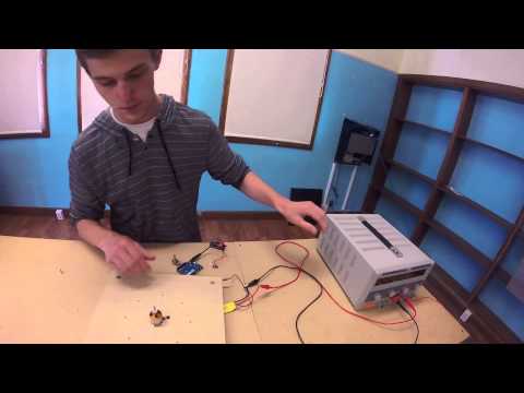
For my first milestone I attached my motor to an ESC (Electronic Speed Controller), an Arduino, and a potentiometer so that I can control the speed of my motor with the potentiometer. I did not have much experience with Arduino going into this project, so the most challenging part of this milestone was researching and learning how to code Arduino online. I coded the Arduino so that it would read the position of the potentiometer and convert it into a value to send the ESC. The ESC then uses that to regulate the speed of the motor.
The code I used to control the speed of the motor
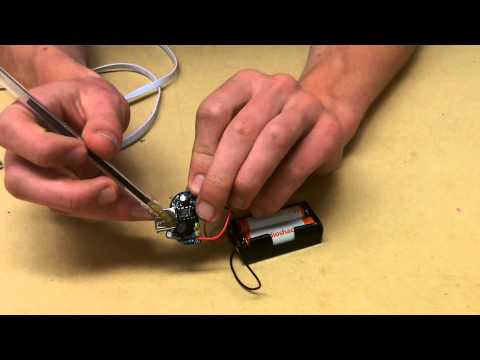
MintyBoost- Starter Project

The full schematic for the MintyBoost from Adafruit
For my Starter Project I built a USB iPhone charger powered by two 1.5 V (AA) batteries. As an iPhone requires a 5V power source, I used a boost converter to convert the 3V input to a 5V output. Boost converters use an automatic switch, a capacitor, an inductor, and a diode to increase a certain input voltage, as you can see in the diagram below.

When the switch is closed, the capacitor stores a charge, and when the switch is open the capacitor releases that charge, increasing the output voltage dramatically. The diode forces current to only flow one way through the circuit, while the inductor uses a coil of wire and a magnetic field to smooth any sudden changes in current, resulting in an output voltage that is the average of the maximum and minimum voltages. I used capacitors and inductors throughout the rest of my circuit to prevent any sudden changes in voltage and current.
In addition to the 5V power source, USB iPhone chargers require a 2V input. I used two resistors in parallel to the rest of the circuit to create a voltage divider and a 2V output for the USB.

Equation and Diagram for a Voltage Divider from the AddOhms Youtube channel