Omnidirectional Robot
Hi, my name is Anant, and I’m an incoming sophomore at Lynbrook High School building an omnidirectional robot. My journey through BlueStamp and experiencing the engineering process has been frustratingly fun and has brought to fruition something beautiful. Let’s follow the steps I took getting there.
Engineer
Anant B
Area of Interest
AI and Robotics
School
Lynbrook High School
Grade
Incoming Sophomore
3rd Milestone
For my third milestone, I added three ultrasonic sensors for obstacle detection. This allows my robot to be PS2 controlled, but move away from obstacles in the exact opposite direction it came from until it is 10 centimeters away from said obstacle, in case the driver isn’t paying attention. Adding the ultrasonic sensors was a daunting and painstakingly slow task, which I achieved again in three steps.
The first step to integrating the three ultrasonic sensors into the robot for obstacle avoidance was figuring out how to get one of them to work, independent of making the robot move . Since my main arduino board and main breadboard were cluttered with wires, I decided to use a completely new pair for testing purposes only. Quickly, I was able to find starter code for the sensor on the internet, and in a span of about 20 minutes, I was able to get the sensor to work. This step posed no challenges, but did teach me about how these ultrasonic sensors work. I learned that the ultrasonic sensors essentially use echolocation, emitting a high-frequency sound every to milliseconds, setting a timer, receiving the echo, and converting the timer’s count to a distance using some simple math.
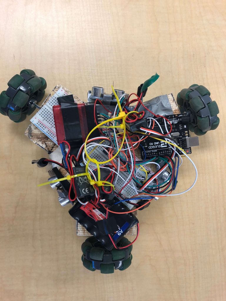
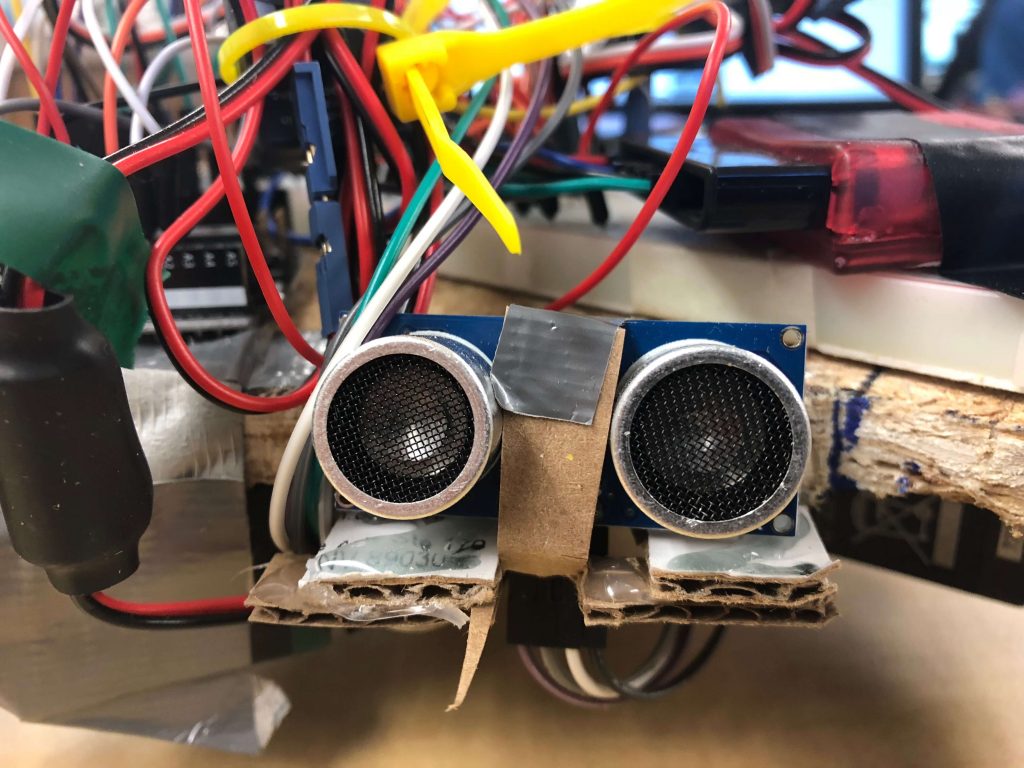
The next step was getting the three ultrasonic sensors to work together and integrating them into the main breadboard and Arduino. When I first tried to get all three of the ultrasonic sensors to work, I had lined them up on the breadboard and tried to get them to return back the appropriate distances. Unfortunately, only one of them decided to work. At first, I thought this was a grounding issue, one similar to the issue I had faced during my work with the servos, but later I realized that it wasn’t. After researching why this wouldn’t work, I learned that the echoes from one sensor would actually interfere with other sensors in close proximity. This was a really quick fix, and soon all three sensors were working perfectly. Next, I mounted the sensors onto my robot. At first, I had just taped them, but this turned out to be a flimsy solution, as the tape and sensors would keep falling off. To fix this, I handmade special cardboard mounts designed to fit the sensors perfectly without interfering with their frequencies. After mounting the sensors, I rewired them onto the main breadboard and Arduino, and everything seemed to work perfectly.
This, of course, was naive, since nothing ever works out the way you want it to in engineering. When I got to integrating the sensors into my main code and adding obstacle avoidance, the whole project seemed to fall apart. I was hoping to get my main code working on the first try, just as I had gotten the other to steps, but the robot seemed to completely disregard the code I put in. I learned that this was happening because my sensors code, or obstacle avoidance code was actually in an else statement, giving it second priority to receiving signals from my controller. This meant that each time my Arduino went through it’s main loop, it would see that it was receiving signals from my controller and skip over the obstacle avoidance code in the else loop. Of course, after I made this fix the robot still didn’t work. Troubleshooting some more, I realized that the scope of one of my variables required for obstacle avoidance was actually too small (it was in the main loop), and wasn’t saving value over different iterations in the loop. I increased the scope of the variable by making it global. I still found bugs in my code, and the robot still didn’t work. So i decided to modularize my code to make it easier to test, since I had loads of repeating code with potential errors. Doing things actually made things a bit better. The robot would avoid a wall the first time, but the next time it would drive straight into it, and then twirl around randomly. I sat their patiently and looked at the functions that I had made. After a good 2 days of debugging, I realized that my methods were the problem, and that the variable I was returning was actually already initialized as a global variable, and therefore wasn’t local. This fixed things but the robot was still inconsistent. I tried simplifying my obstacle avoidance code, and took out a delay that I thought was crucial to the working of the robot. I also added another else statement, which was my dad’s idea, as he said it would set the robot to a resting state, so that you know exactly how it was going through the main loop. After all these fixes, the robot worked, but was still a little sporadic. I wasn’t happy with the results and tried to fix the remaining bugs. This took me another day and a half. I tested the robot 27 times, each and every time resulting in hope-crushing failure. I was about to give up on the obstacle avoidance idea, until an instructor of mine told me to add serial prints to debug what was happening. I did this, but the serial prints were whizzing past my eyes on the serial monitor, too fast too read, so i added a delay of 50 milliseconds. And somehow, this delay fixed almost all the bugs in the robot. I had finally fixed the bug on accident, without exactly knowing what I did. After a week of debugging and writing code, after hours of reading, stomping on the ground; after crushing failures, technical issues, and after almost giving up, I finally fixed almost all the bugs in my robot. Although I did learn about scope and functional programming, as well as a little bit of C++, the thing I learned about most form this milestone was that programming is 10% writing code and 90% debugging, and also the role that if you persevere through problems and try to fix them, never giving up, at some point you are bound to succeed.
Here is my source code for the robot control system. Click right below this heading!
#include <PS2X_lib.h> //for v1.6
#include <Servo.h>
#include <math.h>
PS2X ps2x; // create PS2 Controller Class
Servo myservo;
Servo myservo2;
Servo myservo3;
Servo myservo4;
int error = 0;
byte type = 0;
byte vibrate = 0;
const int trigPin1 = 12;
const int echoPin1 = 13;
const int trigPin2 = 11;
const int echoPin2 = 10;
const int trigPin3 = 2;
const int echoPin3 = 4;
const int trigPin4 = 5;
const int echoPin4 = 3;
int distance1;
int distance2;
int distance3;
int distance4;
int nvmotor1;
int nvmotor2;
int nvmotor3;
int nvmotor4;
//boolean logic = false;
void setup(){
Serial.begin(57600);
pinMode(trigPin1, OUTPUT); // Sets the trigPin as an Output
pinMode(echoPin1, INPUT); // Sets the echoPin as an Input
pinMode(trigPin2, OUTPUT); // Sets the trigPin as an Output
pinMode(echoPin2, INPUT);
pinMode(trigPin3, OUTPUT); // Sets the trigPin as an Output
pinMode(echoPin3, INPUT);
pinMode(trigPin4, OUTPUT); // Sets the trigPin as an Output
pinMode(echoPin4, INPUT);
myservo.attach(A0);
myservo2.attach(A1);
myservo3.attach(A2);
myservo4.attach(A3);
//CHANGES for v1.6 HERE!!! **************PAY ATTENTION*************
error = ps2x.config_gamepad(9,8,7,6, true, true); //setup pins and settings: GamePad(clock, command, attention, data, Pressures?, Rumble?) check for error
}
void loop(){
if(error == 1) //skip loop if no controller found
return;
else { //DualShock Controller
distance1 = finddistance(trigPin1, echoPin1, 1);
distance2 = finddistance(trigPin2, echoPin2, 2);
distance3 = finddistance(trigPin3, echoPin3, 3);
distance4 = finddistance(trigPin4, echoPin4, 4);
ps2x.read_gamepad(false, vibrate); //read controller and set large motor to spin at ‘vibrate’ speed
vibrate = ps2x.Analog(PSAB_BLUE); //this will set the large motor vibrate speed based on
/* I added this to try to fix looping through this first if statement. If the logic variable is wrong, tell me*/
if( ((distance1 < 10) || (distance2 < 10) || (distance3 < 10)) ){
// int temp1 = nvmotor1;
// int temp2 = nvmotor2;
// int temp3 = nvmotor3;
// nvmotor1 = 3000 – nvmotor1;
// nvmotor2 = 3000 – nvmotor2;
// nvmotor3 = 3000 – nvmotor3;
myservo.writeMicroseconds(3000-nvmotor1);
myservo2.writeMicroseconds(3000-nvmotor2);
myservo3.writeMicroseconds(3000-nvmotor3);
// Serial.println(nvmotor1);
// Serial.println(“nvmotor2:”);
// Serial.println(nvmotor2);
// Serial.println(“nvmotor3:”);
// Serial.println(nvmotor3);
delay(5);
// nvmotor1 = temp1;
// nvmotor2 = temp2;
// nvmotor3 = temp3;
}
else if (ps2x.Button(PSB_R1)) // print stick values if either is TRUE
{
int x = ps2x.Analog(PSS_LX);
int y = ps2x.Analog(PSS_LY);
nvmotor1 = runmotors(x, y, 270);
nvmotor2 = runmotors(x, y, 30);
nvmotor3 = runmotors(x, y, 150);
nvmotor4 = runmotors2(x, y, 270);
myservo.writeMicroseconds(nvmotor1);
myservo2.writeMicroseconds(nvmotor2);
myservo3.writeMicroseconds(nvmotor3);
myservo4.write(nvmotor4);
}
else
{
myservo.write(90);
myservo2.write(90);
myservo3.write(90);
}
}
delay(5);
}
int runmotors(int x, int y, int z){
int mapx = map(x,0,255,-100,100);
int mapy = map(y,0,255,-100,100);
double alpha = M_PI-atan2(mapx,mapy);
double squrt = sqrt(mapx*mapx + mapy*mapy);
double vmotor1 = squrt*cos(z*M_PI/180-alpha);
//Serial.println(vmotor1);
int nv = map(vmotor1, -142, 142, 1000, 2000);
//Serial.println(nv);
return nv;
}
int runmotors2(int x, int y, int z){
int mapx = map(x,0,255,-100,100);
int mapy = map(y,0,255,-100,100);
double alpha = M_PI-atan2(mapx,mapy);
double squrt = sqrt(mapx*mapx + mapy*mapy);
double vmotor1 = squrt*cos(z*M_PI/180-alpha);
//Serial.println(vmotor1);
int nv2 = map(vmotor1, -142, 142, 0, 180);
//Serial.println(nv);
return nv2;
}
int finddistance(int trig, int echo, int i){
digitalWrite(trig, LOW);
delayMicroseconds(2);
digitalWrite(trig, HIGH);
delayMicroseconds(10);
digitalWrite(trig, LOW);
long duration1 = pulseIn(echo, HIGH);
int distance= duration1*0.034/2;
return distance;
}
2nd Milestone
In my second milestone, I built my chassis, mounted my servos and Arduino to it, and then coded it to respond to my joystick instead of the pads on my remote. I also made it independent in terms of power supply, as in it wasn’t dependent on my computer to draw power. This was essentially my base project without modifications. I took three steps to achieve my second milestone, which are all listed below.
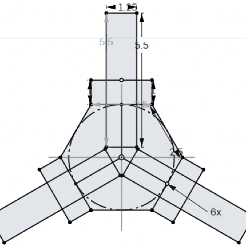
The first part involved building a chassis. The chassis was made of wood, and was designed to be 7.5″ x 6.5″ in size. Because of its size, and the protrusions that gave it it’s drone-like look, the chassis had a lot of perimeter, which meant a lot of sawing. I hand sawed the whole chassis, which took about 2.5 hours. Because of the errors I made while sawing, the chassis also turned out to have a lot of imperfections, which I had to fix with a Dremel ( a Dremel is a power tool used for sanding). I also had to drill holes into the chassis for screws, which I would use to attach the large legs of the chassis to the main body. Here is where I faced the biggest challenge during the building of the chassis. Because of the imperfections created during the hand sawing, the legs which I planned to attach to the body didn’t align with its center. I could have used a Dremel to straighten them out so that they would, but this would have taken hours. Instead, I decided to pivot and took the legs off of my design completely. Through the journey, I learned how to use power tools such as Dremel and drill, as well as the role compromise plays during the engineering process. I learned that things don’t always go the way you planned, and you have to be flexible to deal with these obstacles. The next step in my second milestone involved mounting everything onto my newly built chassis.
The last part of my project involved coding the robot to run with the joystick controls. This was really hard because it involved solving a seemingly impossible physics problem. The question was: “Given an arbitrary velocity, at what speeds should I move each of the wheels so that the robot drives with that velocity and with 0 angular momentum”. I spent about two days trying to understand the solution to the physics problem until I realized its unnecessary because the computer would do the work for me. All I needed to do was figure out the velocities of the three wheels given the arbitrary velocity (v, \theta). This turned out the be the cosine of (30 – \theta) for wheel 1, cos(150 – \theta) for wheel 2, and cos(270 – \theta) for wheel three. Of course, this took me a bit of time and help to figure out since I haven’t taken my Physics course yet. After figuring this out, I tried for 2 days to code this. Unfortunately, it wasn’t working. Something was wrong, even though, logically, everything seemed fine. Then, after looking at someone else’s code, I realized that I hadn’t mapped my value properly. The joystick only gave me values from 0 to 255 in the x and y-direction. Since all the numbers in this range are non-negative, it was impossible to get a negative cosines value, and therefore, it was impossible for me to move left or backward. After looking at the correct code, I realized they mapped the (0,255) to (-100,100), which was essentially a unit circle, allowing their computations to simplify a lot. After fixing this everything seemed to work fine.
Mounting the servos to my chassis presented its own challenges. Because of the way the motor was designed, the drive shaft would move when the motor ran and would wiggle around, which put a lot more stress on the shaft than it needed. Before mounting, this driveshaft needed to be stabilized, for which I needed a new part, a shaft bearing. Of course, I didn’t want to order these shaft bearings and waste more money, so I decided to make them myself with steel bars. I sawed through the steel bars with a hand saw, then super glued shaft transformers onto them, so that the shaft would stay in place instead of wiggling. Unfortunately, the shaft transformers wouldn’t stay on very long because the super glue wasn’t strong enough. So I super glued them and then hot glued them, so that they would stay in place and let the super glue dry. After doing this, the shaft transformers never fell off. Then I was able the super glue my servos to my chassis, and tape everything else on top. This process showed me the invaluability of ingenuity during engineering, and how make-shifting sometimes does the trick.
1st Milestone
For my first milestone, I was able to connect my PS2 receiver and three servos to my Arduino and code the Arduino with a simple program to move the servos. I was then able to connect the receiver to the PS2 controller and move the servos by pushing buttons on the PS2. I did this in three steps:
The first thing I did was try to attach the motor and code it to run by itself, without any event-driven code. I did this by attaching the power and ground of the motor to the respective ports in the Arduino and the I/O pin to the 9th PWM port in the Arduino. I then code a simple if command and got the motor to run. This helped me understand how power runs through an Arduino, how motors work, and how I/O works in an Arduino as well. This was by far the easiest part of my first milestone, and I didn’t face too many challenges while making it. This also set me up for the third part of my first milestone.
The next part of my first milestone involved connecting the PS2 receiver to the Arduino. I followed a schematic to wire all the pins correctly to the Arduino. I faced a lot of challenges during this step. Often times, the receiver wouldn’t connect to the PS2 because of interfering frequencies, sometimes the code would be buggy, and eventually, the receiver broke. I didn’t know it did, because it still flashed it’s lights, and it took me hours of debugging to figure out that the receiver was broken. I also figured out that the receiver would connect to the controller well because the attention pin in the Arduino was loose. Trough the debugging process, I learned about how receivers work, what GROUND and VCC are, and the general process of problem-solving.

The final step involved integrating the previous two and finally being able to control the motor (or three motors in this case) with a PS2 controller. I did this by connecting all three motors to a breadboard, and the GROUND port in the Arduino. The biggest challenge I faced during this was that only two of the three motos would run, and the thrid one wouldn’t receive any current. I spent two hours checking the current and voltage flowing through the system, and also checked the current and voltage requirement s for the motors I was using to see if they were getting enough power. I also decided to change batteries multiple times, none of whice worked. Finally, I realized that the system wasn’t grounded. After grounding the system, I was able to control it perfectly. All three motors would rotate when I pressed the up button.
Starter Project
The starter project helped me develop the fundamental skill of soldering, which I will use later during the building of my main project. I also gained a basic understanding of standard parts used in electrical engineering, such as resistors, transistors, and resonators, all of which will be used during the development of my main project. I didn’t face any problems during the building or soldering of my project. All in all, this project really helped gain an understanding of how basic circuits and systems work and helped me hone fundamental skills which I will use during the construction of my main project.