Introduction
Hello, my name is Alvin and I am a rising senior at Mills High School. For my starter project, I chose to make an ultrasonic parking sensor because I am currently driving and occasionally unsure how close I am to an object when backing up. Making the parking sensor will not only allow me to experience engineering first hand, but it will also help me when driving. For my main project, I chose to make a solar powered USB charger. I wanted to make this the charger because I am extremely fascinated on solar power. The ability to convert the sun’s energy into usable electricity just blows my mind. Throughout this camp, I not only learned how to make this solar powered USB charger, but I also learned how work independently. I had to research everything by myself and when I did have a question, the staff would only direct me towards the right direction. This camp is truly unique and will help me in the future.

Main Project: Solar Powered USB Charger
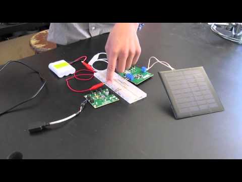
For my main project, I made a solar powered USB charger. It is made up of the solar panel, battery charger, lithium ion batteries, boost, and a female USB drive. The cycle starts off at the solar panel, then goes to the battery charger. At the battery charger, the current is split to the lithium ion battery and and boost. From the boost, the voltage and current goes through to the female USB drive and then to the object being charged.
Check out the Solar Powered USB Charger BOM for the materials!
Schematic

Mechanical Drawing

The purpose of the solar panel is to collect energy from the sun and convert that energy into voltage and current. The battery charger is used to regulate input voltage and reduces charge current so the maximum power point is maintained for maximum efficiency. It also limits the rate at which electric current is added to or drawn from electric batteries, preventing overcharging and preventing against unsafe voltage levels. I chose the lithium ion battery because it has a higher energy density, meaning it stores more energy. It also operate at higher voltages compared to other rechargeables, typically about 3.7 volts for lithium-ion vs. 1.2 volts for NiMH or NiCd. It has a lower self discharge, meaning it retains its charge longer than other batteries. The boost provides 5V output for USB devices. Increases the voltage and reduces the number of cells. The way the boost works is a switch (MOSFET) will create a current through the inductor. The switch then switches off, causing current to not flow. The inductor then attempts to keep the current flowing, therefore, boosting the voltage ( turning its stored magnetic energy into electrical energy). The new electricity, at high voltage, but low current, travels into a capacitor, which stores energy that the inductor discharges. When the inductor almost fully discharges, the switch then turns on, starting the whole process again. The female USB port is connected to the boost which allows regular USB sticks to connect into the circuit.

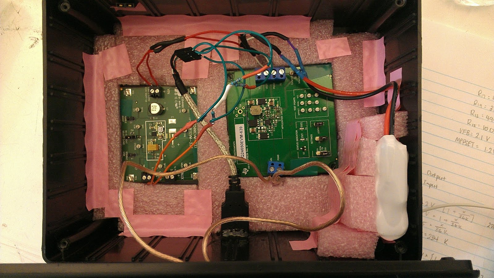
In this project, I also encountered some problems. The battery charger that I had was able to be customized, meaning you can change how much voltage it takes in and gives out. I used the equation they gave us for the output for VFB, VFB= 2.1V * [ 1+ (R13/R15)]. By plugging in 9 volts, the maximum voltage I needed for my circuit, I was able to solve for a resistor value of 220 K ohms for R13 to generate 8.5 volts. Although this value is not exactly 9 volts, it is close enough to not make a dramatic difference. Following that, I also had to change the resistor value for the output of the MPPSET, which was MPPSET= 1.2V * [ 1 + (R17/R19). Using this equation, I was able to solve for a resistor value of 100 K ohms at R17 so the maximum output voltage would be 4.2 volts. To change the resistors on the circuit board, I had to first solder off the original resistors on the board. Then, I had to solder on the replacing resistors.
R13- 220 K ohm resistor
R17- 100 K ohm resistor

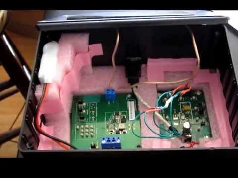
As an extension to my project, I made my charger able to charge iPhones and also secured all the components inside the board. iPhone chargers are very unique because unlike other chargers, they have voltage going through their data pins in the USB. To make the pins have voltage, I had to add two 560K ohm and two 150K ohm resistors onto the USB portion of my components. This would enable the iPhone to obtain the 5V for charging and about 2V for the data pins. I also placed styrofoam into my box and taped all the components into the box, securing it. Even when upside down, nothing in the box fell down.

Starter Project: Ultrasonic Parking Sensor
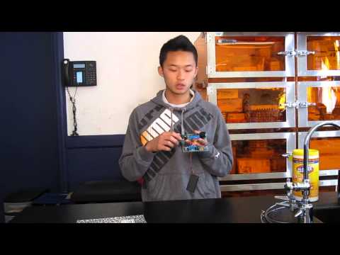
For my starter project, I made an ultrasonic parking sensor. The parking sensor sends out sound waves to detect proximity to an object. The sensor measures the time it takes for the sound waves to hit the object and bounce back. As the object moves closer to the sensor, the buzzer sounds.
First, one sensor sends out the sound waves and the other sensor picks up the sound waves. The waves then get converted into an electrical current in the sensors and sent through the screw connectors that connect the receiver board to the main board. The current then gets passed onto the chips on the IC sockets. Two of the chips control the relationship between the sensor and buzzer and determines whether or not the buzzer sounds. The other four act as op-amps, or amplifiers for the signal. Throughout the circuit board are diodes, resistors, capacitors, and electrolytic capacitors.. Diodes are used to allow the flow of current in only one direction. Resistors are the resistance in the electrical current. It is also used to maintain the voltage within the circuit board. The capacitors are used to store energy. The different colored stripes on the capacitors determine the amount of Ohms it has. The electrolytic capacitors are designed to store more electricity than the regular capacitor. They are also polar, which means current only flows in one direction because it has a positive and negative end. A few other important materials in the circuit board are the trim potentiometer, quartz crystal, and the transistor. The trim potentiometer changes the sensitivity of the sensors. The quartz crystal sets a specific frequency throughout the board. The transistor turns the circuit board on and off. When the parking sensor is placed in the car, the board automatically turns on when the car is placed on reverse. Throughout this whole project, I not only learned the different parts of a parking sensor, but I also learned how to solder and build the circuit board.