Motion Activated Music Player
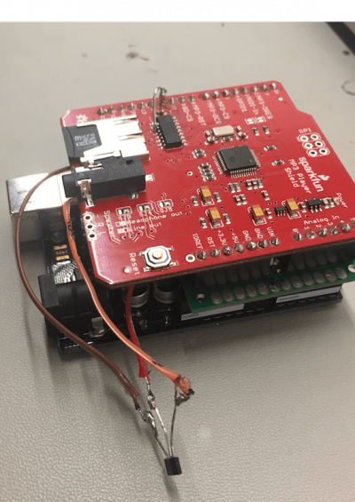
The Motion Activated Music Player starts playing music when a door is opened. A magnet is attached to the door, which, when opened, exposes a magnetic field to a hall effect sensor, attached to the wall, and triggers an mp3 file to play music through the speakers.
Engineer
Aliza Meller
Area of Interest
Electrical Engineering and Mechanical Engineering
School
SAR High School
Grade
Incoming Senior
Final Milestone
Reflection
Before attending Bluestamp Engineering, I had minimal experience with Arduino and almost no understanding of the worlds of mechanical and electrical engineering. Bluestamp Engineering has sparked my interest in these two areas so much so that I plan on pursing mechanical and electrical engineering professionally as I delve deeper into the intricacies of engineering in college. This program has helped me learn more about my interests and capabilities and I hope to continue my personal journey on my path to becoming an engineer.
I completed my final milestone for the motion activated music player! Instead of assembling my project to an actual door, I created a miniature door out of cardboard and attached the magnet as the door handle. When the door is open, the magnet passes by the hall effect sensor and triggers ACDC’s “Highway to Hell” for 18 seconds. I downloaded the song as an MP3 file and named it “track004.mp3”. I was also able to figure out how to make the song stop after 18 seconds by adjusting the volume after the given amount of time. The most challenging part of this milestone was getting the door to stand. I attempted to make a stand using cardboard and tape, but after that failed I used screws and L clamps to construct stands. I also used screws to attach the arduino to the wall next to the door. As this part of the project was more for aesthetic purposes, it was less enjoyable than the other milestones, but helped my project look more presentable and effective for its main purpose.
Second Milestone
I completed the code for my project which connects the hall effect sensor and the mp3 player. In this process, I downloaded the libraries for the mp3 player and put a file on the microSD card and named it “track001.mp3”. I wrote the code for the hall effect sensor and the mp3 player separately, and once those both worked, I combined them into one code that allows for the hall effect sensor to trigger an mp3 file once a magnet passes by it. A challenge I faced when writing this code was that I would constantly run a code, but it wouldn’t work and figuring out the problem seemed impossible. Plus, when I figured out what was wrong, and it still didn’t work, I would have to go back from square one to find the problem. I also kept breaking the header pins that attached the mp3 player shield to the arduino and the proto shield which was extremely difficult to have to redo. However, when I finally fixed all of my problems, I was able to figure out the code that pulled all of my components together into one unit. I also got rid of the push button component because I coded the music player in a way that it stopped after a certain period of time. All in all, I liked this part of my project because of the accomplishing feeling I felt after I finally fixed everything and got my project to work.

#include <SPI.h>
#include <SdFat.h>
#include <SFEMP3Shield.h>
SdFat sd;
SFEMP3Shield MP3player;
volatile byte half_revolutions;
unsigned int rpm;
unsigned long timeold;
void setup() {
Serial.begin(9600);
//start the shield
sd.begin(SD_SEL, SPI_HALF_SPEED);
MP3player.begin();
MP3player.setVolume(0,0);
half_revolutions = 0;
rpm = 0;
timeold = 0;
}
void loop() {
if (!digitalRead(5)) {
Serial.println (“detected”);
//start playing track 1
MP3player.playTrack(1);
delay(750);
}
}
volatile byte half_revolutions;
unsigned int rpm;
unsigned long timeold;
void setup()
{
Serial.begin(9600);
half_revolutions = 0;
rpm = 0;
timeold = 0;
}
void loop()//Measure RPM
{
if (!digitalRead(5)) {
Serial.println (“detected”);
}
}
#include <SPI.h>
#include <SdFat.h>
#include <SFEMP3Shield.h>
SdFat sd;
SFEMP3Shield MP3player;
void setup() {
Serial.begin(9600);
//start the shield
sd.begin(SD_SEL, SPI_HALF_SPEED);
MP3player.begin();
//start playing track 1
MP3player.playTrack(1);
}
void loop() {
Serial.println(“MP3 Player Works!”);
delay(2000);
}
First Milestone
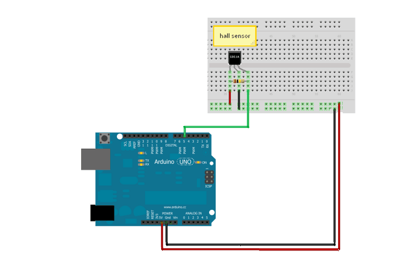
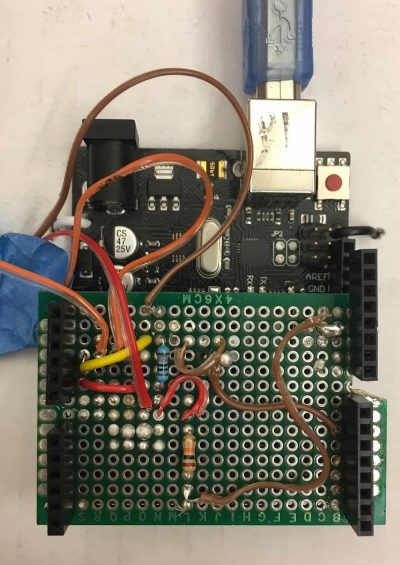
I completed the electrical part of my project. First, I made the circuit on a breadboard which included a hall effect sensor and a push button. The hall effect sensor in my project senses the presence of a magnetic field––when a magnet is brought close to it––and changes the output voltage which triggers an mp3 file on the mp3 player shield. The push button serves as an emergency stop button and immediately stops the music when it’s pushed. After following a sample code from arduino to test both the hall effect sensor and the push button, I moved the circuit onto the proto shield that I made by soldering female header pins on a stripboard and soldered the circuit on that shield. I then tested the hall effect sensor and the push button through the proto shield to make sure I soldered all the wires and resistors correctly. A challenge I encountered when completing this milestone was that the soldering took lots of time and making the bridges between the holes on the proto shield was frustrating as I would make a bridge and then accidentally break it and have to solder it again. This challenge lasted throughout most of the soldering, but in the end, the hall effect sensor and the push button both worked which demonstrated that although it took a while, I soldered effectively and correctly. I liked soldering, even though it took a while, and felt a sense of accomplishment when the push button and the hall effect sensor worked.


