3D-Printed Robotic Arm
My main project at Bluestamp Engineering was a robotic arm made out of 3D-printed pieces. It is controlled with a glove, which it mimics.
Engineer
Alexander Y.
Area of Interest
Computer Science
School
Menlo-Atherton High School
Grade
Incoming Junior
Alexander Y. Bluestamp Engineering Documentation
Demo Night Presentation
This is my Demo Night presentation. It’s more or less my second modification video, as I didn’t fully complete the modification to add the rest of the arm, so I didn’t film it. However, you can see it here. The elbow and rotation joint both work off of gear assemblies, powered by a DC motor. I would have liked to use an H-bridge to control the motors, and to connect that to my Arduino, but I ran out of time to execute on that plan.
Overall at Bluestamp, the coolest problem I worked on was my circuit design. It took me a fair amount of time to work it all out, which only increased as I made modifications to my project. My favorite experiences at Bluestamp mostly include figuring out the solutions to problems, like how to fit my voltage regulator into my circuit while keeping the rest of the design the same. After Bluestamp, I feel inspired to explore engineering more so than I would have before, as I now have much more experience in mechanical and electrical engineering.
You can find my code, plans, and materials that I used on my Github, here.
First Modification
My first modification was to add wireless communication between the glove and the arm, so that they didn’t have to be tethered to each other at all times. I used two NRF24L01 wireless communication modules, one connected to my original Uno board, and the second connected to a separate Arduino Nano board.
The code to connect the two boards wasn’t all that complicated, I just had to specify an address and a power level for communications, and then start sending data. The transmitter (the Uno) measures the values from the flex sensors and sends them (translated into degrees) as an array of values. The receiver (the Nano) takes these values and drives the servos to match them. Both of the boards can be powered with portable batteries or a computer.
Some challenges I had arose from creating essentially a whole new circuit for the receiver. I used a rather small board, so that it might fit into the arm, or at least be lightweight. However, because there were so many wires that I had to solder and bridge in such a small space, I ended up burning many of them. It worked out in the end, though.
Slightly unrelatedly, I also installed the forearm cover on the arm, so that the servos are no longer exposed. It’s mostly for asthetics.
Final Milestone
My final milestone was to connect the main circuit from my second milestone with the 3D-printed hand from my third milestone.
Basically, what I had to do was take the wires going to the servos that weren’t inside of the hand, and connect them to the servos that were inside of the hand. After much fine-tuning of values in the code and tightening of screws and wires, the hand worked.
In addition, I moved from powering the Arduino with my laptop to powering it with a portable battery. This helps the arm to be at least slightly more portable.
Now that I’m done with the main goal of my project, I plan to make some modifications, including building more of the arm, making the control circuit and the arm communicate wirelessly, and getting a vision system in place instead of the glove to control the arm.
The code and final schematic for my project can be found here.
Third Milestone
My third milestone was to assemble the 3D-printed hand and attach the servos.
To complete this milestone, I disconnected the servos from the main circuit so I could wire them up. The hand has a bunch of little joint pieces that get connected with screws. Those get attached to the palm, which is then attached to the forearm. The servos go inside the forearm. Finally, small fishing wire is run through the fingers to the servos, which allows the servos to bend the fingers. The wires for the servos go out the bottom of the arm, where I can connect them to the main circuit in the future.
I initally used much thicker fishing wire, but it got stuck within the joints and restricted movement. I then tried to use elastic, but it was so flexible that I couldn’t get it down the channels within the hand, and it couldn’t control the hand because it gave too much. I settled on a thinner fishing wire, which was the best of both worlds.
The files and design for the hand/arm came from here.
Second Milestone
My second milestone was to finish the sensor/servo circuit and sew it and the sensors onto the hand.
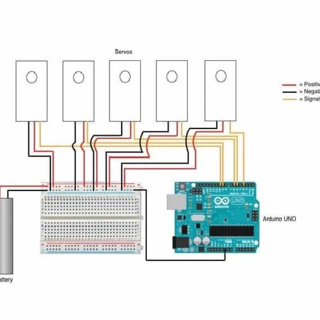
The circuit is made of one blank board, which handles both the sensor’s signals and the servos’ power delivery. The components are connected with solder bridges. The circuit is connected to the flex sensors, which have been attached to the fingers of the glove. The glove is wearable, and the servos will turn when the fingers flex.
One major change I made to the circuit was the addition of a voltage regulator circuit, involving a step-down voltage regulator that converts the 7.2 volts that the battery puts out to the 5 volts that the servos can handle. This change required a big change to the power delivery portion of my circuit, as the servos had to get a control wire from the arduino, and power from the battery, essentially on two separate circuits.
To complete this milestone, I had to learn about proto boards and how to work with them. One challenge I faced from not having worked with proto boards before was when I had to connect everything by bridging the holes in the board with solder. A lot of the solder either collected into one large blob on one hole, or accidentally connected with another bridge. In the end, however, I got it working.
First Milestone
My first milestone for my main project at Bluestamp Engineering was the prototype of the flex sensor/servo control circuits, in addition to the code that puts them together.
The entire circuit is located on one solderless breadboard currently, because it is a prototype. Essentially, the flex sensors control their respective servos through the amount of current that runs through them. When bent, their electrical resistance increases. The arduino measures this from the difference between the 5V it puts in and what comes back. It maps the value it receives into a corresponding amount of degrees, and turns the servos to the point they should each rotate to with PWM.
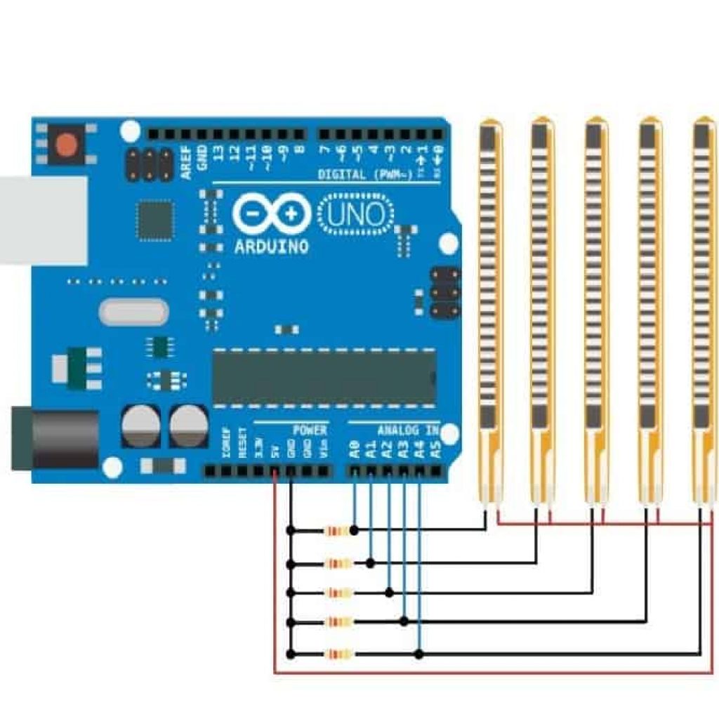
My circuit designs come from here. It actually took me 4 separate tries to get the circuit working correctly. But finally, I got it done, and with the battery too. I had been using a power supply to test, but it wasn’t portable. The code that controls both the servos and the flex sensors is relatively simple, as described above. My plans are now to create the PCB to be sewn into the glove, and attach the flex sensors to the glove as well.
Starter Project – MiniPOV 4
My starter project at Bluestamp Engineering was the MiniPOV kit from Adafruit. MiniPOV stands for Mini Persistence Of Vision. The completed module has 8 RBG LEDs that are controlled by a ATMEGA328P-PU microcontroller. You can upload an image to the module, and when next turned on, it will flash its LEDs so that if you wave the module back and forth, it will display an image! A dark room (and maybe a long-exposure camera) are necessary to fully see the effect of the MiniPOV.
The MiniPOV uses standard electronics components to work, including resistors, capacitors, transistors, diodes, and a potentiometer. In addition, it uses some slightly more specialized parts, like an oscillator, the LEDs, a USB-B jack, a battery holder, a PCB designed for it, and the microcontroller. The resistors lessen the voltage going to each LED so as not to burn them out. The capacitors save a small amount of current to account for small breaks in current coming from the battery. The transistors and diodes route current throughout the board. The potentiometer can be turned to adjust the amount of current going to the oscillator, which in turn controls how fast the LEDs move to the next row of pixels in the loaded image. The battery holder and USB jack connect batteries and a USB cord to the microcontroller, respectively.
I had nearly no problems assembling the kit, except for when I had to solder the battery holder’s wires into the PCB. Both the positive and negative cables had multiple smaller wires inside of them, so I decided to solder them together to make them more stable. However, the soldered cables ended up being to large to fit into the PCB. So, I solved this problem by soldering the cables from the battery holder to small pieces of wire which I would then connect to the PCB. This worked fine in the end, and I covered up the soldered area with electrical tape. I credit my relatively successful final product to having electronics experience from a radio that I made about two years ago, a very similar, if more generic project.