Remote Controlled Robot
My project is a robot that can be controlled by a PS2 controller. The robot also has a crash avoidance feature. In the future I would like to make my robot fully autonomous.
Engineer
Alex B
Area of Interest
Electrical Engineering, Mechanical Engineering
School
Lick-Wilmerding High School
Grade
Incoming Senior
Reflection
I surprised myself completing my PS2 controlled robot project. It was fairly complex and I was able to finish it in about a week and within that week I was able to add the crash avoidance feature. I proved to myself that I was capable of working on complex electrical engineering problems. This project also helped me a lot with debugging and learning how to solve problems by myself. I spent half a day just trying to pair the PS2 controller to the receiver. I successfully resolved the problem and through this process learned and developed problem solving and critical thinking skills.
In the future I would like to make my robot fully autonomous. I would also like to make multiple robots that could operate under swarm intelligence and communicate to each other using wireless transmitters and receivers.
Main Project – Robot controlled by PS2 controller
A Summary of My PS2 controlled robot project:
Modification #1:
After I finished my base project of the PS2 controlled robot, I wanted to add a crash avoidance feature. I have now added an ultrasonic sensor (see photo at top of page) and I used the sensor to implement this feature. The ultrasonic sensor works by constantly sending out sound waves. When those sound waves bounce off of an object, the ultrasonic sensor detects the returning sound waves through the receiving side of the sensor. Inside the sensor there is a micro controller that times how long it takes for the sound wave to bounce off of the object and come back to the sensor. Because the speed of sound through air is known and constant (given constant air pressure), the distance can be found. The way my crash avoidance works is when the Arduino detects a reading from the ultrasonic sensor that is less than 30 cm, the Arduino will tell the DC motors to stop and then reverse for one second.
Base Project:
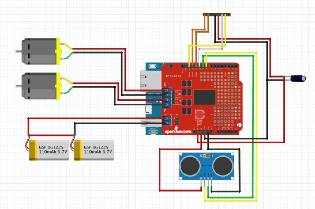
My Robot I built is an Adafruit mini 3 layer chassis powered by 2 DC motors. The micro controller was an Arduino Uno and I also used the Adafruit motor shield to make assembly easier. The robot is powered by a 2 cell Li-ion battery. The PS2 controller and receiver were from a generic brand called “TPFOON“.
The actual assembly was fairly straightforward. I had to solder the motor shield to the pins and had to connect the leads from the receiver to the digital pins of the Arduino. The chassis was also easy to assemble. When it came to programming the Arduino and interfacing the PS2, I had some problems. There was not a ton of documentation for the PS2x library and there were only a few examples online. Initially, I also had a hard time having the Arduino and receiver recognize that the controller was connected. After several hours of trouble shooting, I accidentally pressed the “mode” button on the controller and it instantly connected. I also installed a small capacitor along the power line to the receiver to decouple power supply from the receiver. I had read on a online forum that the receiver was sensitive to power inconsistencies so adding this capacitor fixed that issue. After the problems with the PS2 controller, the rest of the coding went smoothly with only a few a issues like motor control.
Pressing the right trigger will start the robot and pressing the “X” button will stop the robot. The right joystick of the controller controls the steering. The robot tracks straight and the steering works well.
In the future, I would like to make some modifications to my robot. I want to add an ultrasonic sensor so that I can program a crash avoidance system. I also think it would be cool to have the robot drive totally autonomously.
Important Links
Here is the schematic of my Robot. The 8 pin header represents the PS2 receiver.
PS2 Crash Avoiding Robot Schematic

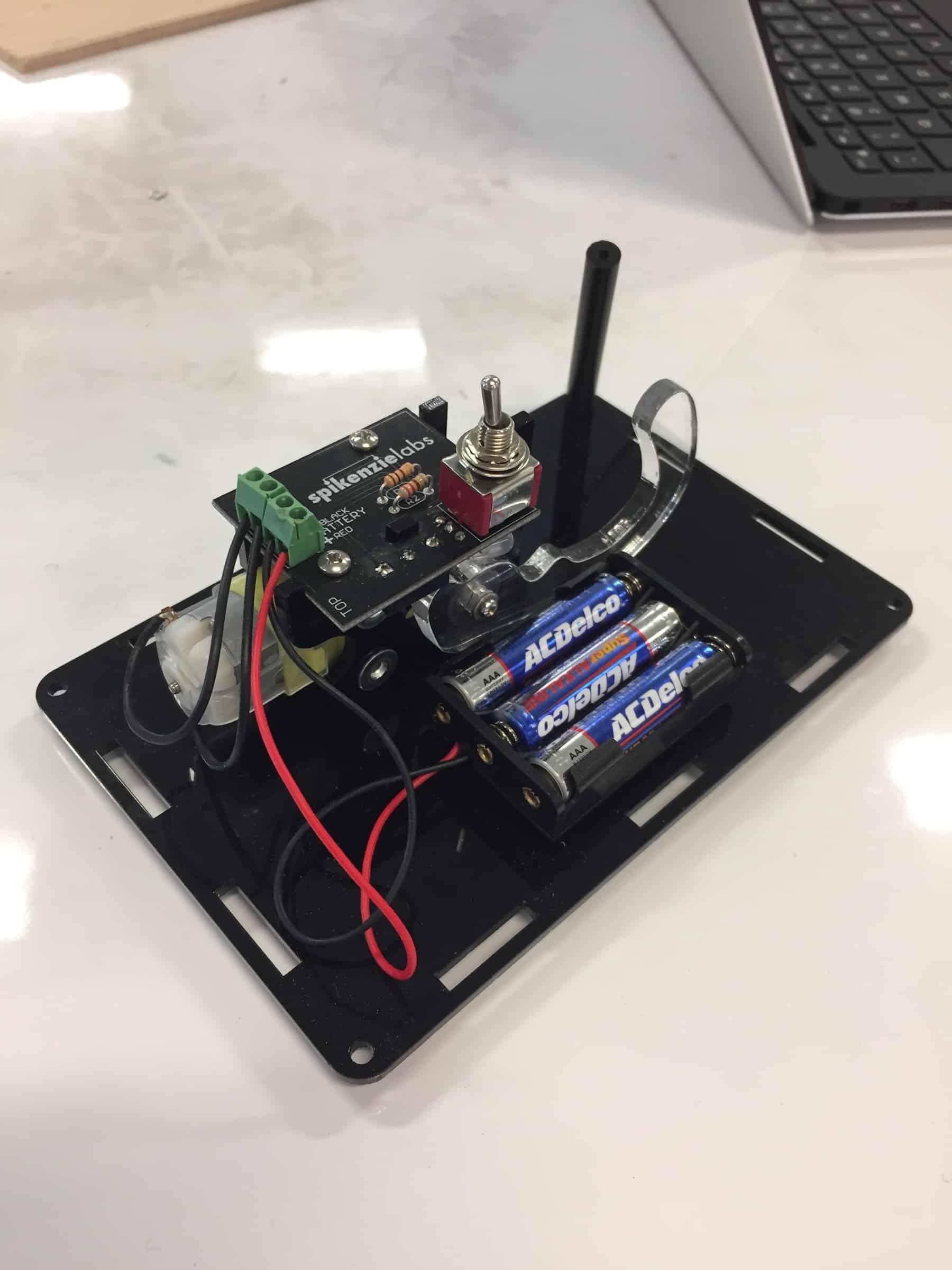
Useless Machine


