Automatic Plant-watering Device
I am making a device that waters plants when they need water. It uses sensors in the water cup and the plant pot to detect if there is water in both. The pump will pump water from the water cup to the plant pot when the sensor in the soil detects that there is no water there.
Engineer
Aidan K.
Area of Interest
Automation
School
York Preparatory School
Grade
Incoming Junior
Final Milestone
I made an automatic plant-waterer.
How It Works There are two containers, one for water and one for the plant, each with two aluminum strips attached to sensor wires that go back to a circuit attached to arduino. The aluminum strips detect the presence of water in the containers by sending electricity through one of the strips and waiting for water to conduct a portion of it to the other strip. The arduino is programmed to give power to a submersible water pump in the water container only if there is water in the water container and there is no water detected in the plant’s container.
Changes I’ve made a couple major changes since my last video, the most notable being the addition of the arduino Uno, which happened on Tuesday, after I realized that my previous circuit was not sensitive to detect water. (It could detect about a thousand ohms of resistance, but water is much more resistant.) Instead of trying to figure out what was wrong with my old circuit, I built a newer, slightly simpler circuit that is aided by the Arduino Uno. Aside from being easier to troubleshoot and set up, the Arduino also enables me to more easily upgrade my project in the future, should I wish to do so.
I used screw terminals to attach my sensor and motor wires to my circuit instead of directly soldering them to my circuit.
Challenges The major challenge was the scramble of suddenly realizing on the day before I had to present my project in front of an audience, that my project didn’t even work. As you can see, I overcame that.
The screw terminals that I praised earlier may have also been what caused the project to malfunction while I was presenting it on Demo Night. One of the terminals hadn’t been tightened enough and the sensor wire in it had exposed metal coming out of it. I think it touched the other sensor wire and prevented the pump from running. Regardless of that, the screw terminals are still definitely better than what I had before.
It was a little bit difficult to mount because the perfboard extended off of the arduino and one of the arduino’s screw holes was higher than the edge of the box. So, I ended up screwing one of the screw holes into the wood and just hot-gluing the other one.
Reflection I learned a lot from this. For example, I was alerted to the existence of screw terminals.
I am thankful to BlueStamp for giving me the opportunity to learn how to and then to build something I wanted to build.
I used screw terminals to attach my sensor and motor wires to my circuit instead of directly soldering them to my circuit.
The screw terminals that I praised earlier may have also been what caused the project to malfunction while I was presenting it on Demo Night. One of the terminals hadn’t been tightened enough and the sensor wire in it had exposed metal coming out of it. I think it touched the other sensor wire and prevented the pump from running. Regardless of that, the screw terminals are still definitely better than what I had before.
It was a little bit difficult to mount because the perfboard extended off of the arduino and one of the arduino’s screw holes was higher than the edge of the box. So, I ended up screwing one of the screw holes into the wood and just hot-gluing the other one.
int sen1 = 12;
int sen2 = 13;
int mot = 10;
void setup() {
pinMode(mot, OUTPUT);
pinMode(sen1, INPUT);
pinMode(sen2, INPUT);
Serial.begin(9600);
}
void loop() {
if (digitalRead(sen1)) {
Serial.println(“Sen1 triggered”);
digitalWrite(mot, LOW); // turn the LED on (HIGH is the voltage level)
}
else if (digitalRead(sen2)) {
Serial.println(“Sen2 triggered”);
digitalWrite(mot, HIGH); // turn the LED off by making the voltage LOW
}
else{
Serial.println(“Neither triggered”);
digitalWrite(mot, LOW);
}
}
Bill of Materials
Second Milestone
What I made I made an automatic plant-waterer that waters a plant when there’s no water in it. In this milestone, I have soldered the componenents onto a perfboard to make my circuit more permanent.
How it works There are two containers: one for water and another for soil. There are two aluminum foils strips attached to one of the sides of the inside of each container. When there is water in either container, it conducts electricity between the aluminum foil strips, activating the sensor. If there is no water in the soil container, and there is water in the water container, a submersible water pump in the water container will pump water through some tubing into the soil container. The water will stop pumping if the aluminum foil strips detect water in the soil container or if the water-sensing alumninum foil strips detect a lack of water in the water container. It’s currently powered by an Anker battery which connects to the circuit using a USB-A to microUSB cable. In the future, I can connect the cable to an outlet adapter instead of a portable battery.
Challenges So, soldering wasn’t that hard, but it took forever. As I was building this, I was referring to my breadboard circuit for reference, which I also had a Fritzing diagram of on my computer. I noticed two extra components and removed them from the breadboard and the schematic, and I did not add them to my perfboard. When I was finally done soldering, I plugged my new circuit into the power, the motor, and the sensors after I disconnected the breadboard circuit. I had to use the power adapter on the breadboard because I didn’t have another one. As soon as it had power, the pump began to send water through the tubing into the soil. This was strange, because I was quite certain I’d given the soil more than enough water in the past few days, and that shouldn’t have changed because there was no plant to absorb the water. Then, I realized that water was leaking through a crack in the soil container and into the wooden box I had the project in. Fortunately, the circuit was not in the box and none of my electronics got wet. I used up several paper towels in order to absorb the water. Before I left, I put scotch tape over the cracks as a temporary solution, and left a few napkins under the container in case it leaks overnight. At the time of writing this, I have not yet checked to see how well it survived overnight. I have my fingers crossed.
Reflection I learned a lot and I really enjoyed soldering the components onto the perfboard. It wasn’t all easy, but it was fun.
First Milestone
What I made I made an automatic plant waterer that waters a plant when it detects that the plant has no water. At the moment, I don’t have a plant to use it on, so it just waters a container full of soil. Right now, the circuit is working on a breadboard (my first milestone), which means that it should work on a perfboard as well.
How it works There are two containers: one with water and another with soil. Each container has two strips of aluminum foil that are each clipped to wires leading back to the circuit board. One of the wires from each container goes to power and the other wire from each container goes to another part of the board. It is powered by an anker battery connected with a USB A to micro USB cord. This means that in the future, I can use an adapter to plug it into an outlet instead of a portable battery.
Challenges My circuit wasn’t working because I did not realize I needed to attach two sensor wires into power. Ian explained this to me after helping re-wire my circuit. When I first went to record the video, I tried to remove some water from the tube—which I did, only I moved right onto the breadboard. So, Ian told me to unplug everything and poor alcohol on it. He meant that I should just unplug power, but by the time he clarified that, I had already yanked a few things out. So, I had to dry the alcohol and then reconstruct the circuit based on pictures I had of it. Then, I tested it and went to film the video. I then spent about five minutes in the video room trying to figure out why it wasn’t working. I got box to put it in so that I wouldn’t have to take it apart when carrying it, which was how I had run into the problem. Just as I was giving up and packing it up so that I could go back to the other room and fix it, I noticed the wires from the pump hanging off of the table. I had never plugged it in. So, I put some tape over an exposed part of the pump wire that I found, and then I plugged the pump in and recorded.
Reflection I learned a lot from the experience and I now have a better understanding of how my circuit works. My next step is to duplicate the breadboard circuit on a perfboard.

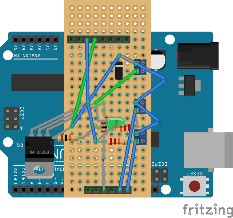
This schematic is not entirely correct and was later modified. The top resistor and the yellow wire that goes horizontally are both in the wrong column (where they are in the same column.) Both of those ends should be in column 23. Later on in my project, I removed a few components from this design before giving up on this fundamental design and opting for an arduino.
What I Made My starter project was a Simon Says kit from sparkfun. Powered by two AA batteries, it features a board of four translucent membrane buttons screwed onto a panel on the board over four corresponding LEDs. There are two 0.1μF capacitors which store electric charge until it is necessary. There is one 10K ohm resistor, which applies resistance (duh), so that a greater voltage is necessary for electricity to flow through.
Challenges I faced two major challenges in this project. The first one was solder bridges—unwanted connections between solder points created by extra solder. I had many solder bridges on the solder points on the microcontroller, which I fixed by melting the solder between the points and pushed the solder onto the individual points. After I had put my soldering iron away, I noticed another solder bridge between two of the three pins for the power switch. To remove the bridge, I simply cut away the excess solder with snippers. The next challenge I faced was with one of the battery connectors. When I soldered it, I hadn’t realized that it was slightly tilted backwards. This meant that the battery did not touch both sides of the holder, preventing the device from turning on. In order to fix this, I first tried to de-solder one of the points on the holder by melting the solder and then wicking it away. I was unable to successfully get rid of the solder this way, so I also tried snipping away the solder with the snippers. I removed some solder, but I was unable to move the battery holder. I then tried to poke through from the battery side with the lead I had cut off another component. Instead of breaking through the solder, I broke through the skin on my finger and nearly the whole pin went into my skin. I immediately pulled it out and I was bleeding. I squeezed my finger and stopped the bleeding in less than a minute. I knew that I could not continue trying to poke through the metal this way, because I did not want to stab my finger again. I then tried poking through by holding the lead with the snippers, but I was still unable to make significant progress. Eventually, Jessie came to the rescue. She bent the end of the battery holder with her finger, so that it would touch the battery. So, the holder is still slanted, but it works now. I had been overthinking it the whole time.
Reflection Overall, I enjoyed the experience and I learned a lot. The only things I didn’t enjoy were when I stabbed my right index finger with the lead and when I slightly burned by right ring finger with the soldering iron. Even those experiences, however, were valuable learning experiences.
STEM Summer
Camps
Code Classes
Coding & Robotics Classes
For Kids in
San Francisco
New York
Denver
Palo Alto