Hi, my name is AJ. I go to Ramaz Upper School , and I had an amazing time working at BlueStamp. I started out by making a voice changer. I felt this was the best project for me to start out with because it seemed like a cool, fun thing to make, but was hard enough to make me learn about basic engineering. After I finished the voice changer I went on to my main project, an EKG heart rate monitor. I always had an interest in both science and engineering and I felt this was a great blend of the two subjects. Also, it seemed like a project that could give me a good challenge, as I would really have to work hard to complete it. I did not want to do a project that was very easy, where I would barely learn anything. Looking back on my experience at BlueStamp, I only have a couple of regrets. The first is that the Intstructable for my project came with a link to the code for my project, and my starter project did not need any code, so I didn’t get any experience in coding, whichI would have liked. Secondly, my project did not require any mechanical engineering so I did not learn how to use any of the power tools in the back. All in all, I had a fun time at BlueStamp and I am happy that participating in this program helped further my interest in engineering.
h Milestone 3 h
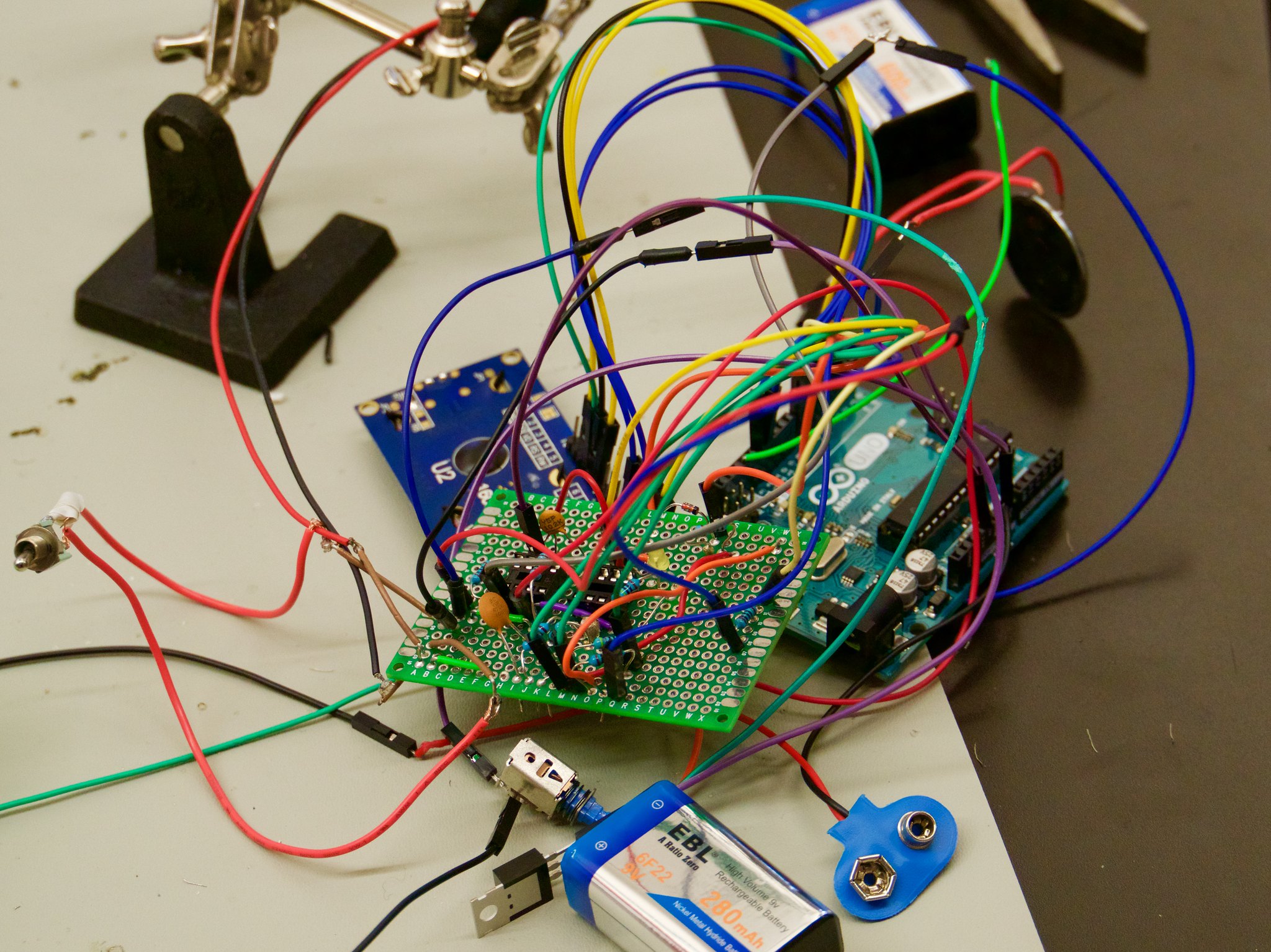
Abraham D - Final Milestone
For my second milestone I got my EKG heart rate monitor following this example, EKG Heart Rate Monitor to detect my heart beat. It was actually very difficult to achieve this. For one thing, the skin that is visible on the chest is all dead skin, and that acts as a resistor against an already faint heart rate. To combat the dead skin’s resistance, I had to use this goo called electrode gel, which was a conductive gel that went on to the electrodes. Also each day when I took my project out or put it away, a lot of connections would come loose without my knowledge so everyday I would have to constantly recheck all connections on my breadboard. Finally, the two IC chips I was using got damaged due to electrostatic discharge. That means that if someone touched the IC chips I was using, they might become damaged due to an electrostatic signal the body sends to the IC chip. The way to combat this is to be grounded by using an antistatic wrist band. For my modifications I hope to put everything into an electrical box, transfer all of my circuit elements to a perforated board, and use real electrodes for a better connections.
hMilestone 1h
Abraham D - 1st Milestone
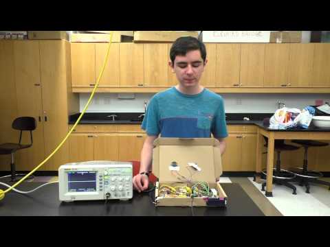
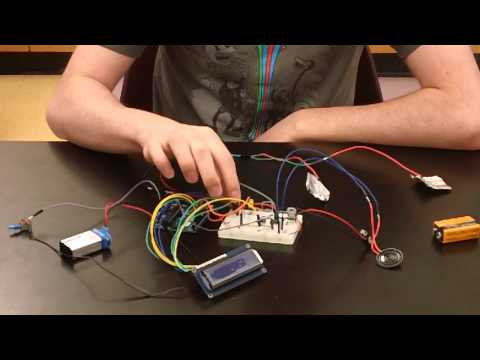
For my main project I am building an EKG heart rate monitor following this example, EKG Heart Rate Monitor. For my first milestone I got all of the circuitry working, although it still needs to be able to pick up the heart rate. What happens is the electrical pulse of the heart goes to the instrumentation amplifier where all the excess noise of the body is filtered out. Then the current goes to the operational amplifier (op amp) where the voltage is amplified so the Arduino has an easier time reading the heart beat. All of the resistors and capacitors around it are to ensure that it actually functions as an amplifier because if different capacitors and resistors with different capacitances and resistances were placed around it differently, it may function as a different type of amplifier. The voltage regulator on the bottom left of the breadboard helps power the op amp. The op amp needs positive and negative voltage to power up, but the batteries only give positive voltage so the voltage regulator negates the value of the batteries voltage in order to power the op amp. Then from the op amp the signal is passed onto the Arduino and then onto the liquid crystal display (LCD) where it shows if the user is alive or dead. The LED will blink with each beat of the heart and the mini speaker sounds out your heart beat.
A major problem I had was breadboard organization. The LCD itself has 16 pins and there were still a lot more components to connect so I had trouble keeping track of everything. I actually burned through two voltage regulators. After I organized my breadboard all of the circuitry worked and was easier to check if needed.
hStarter Projecth
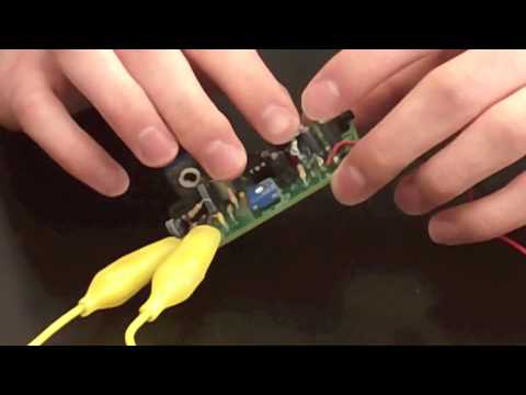
Abraham D - Starter Project
For my starter project I built a voice changer from Apogeekits with the speaker from Sparkfun. The PCB had four buttons on it to choose which kind of voice you want, high pitch, low pitch, vibrato, or robot. The user speaks in the microphone, and the voice, as audio waves, goes to the bigger IC chip, which is basically the brains of the PCB. Depending on the button for what voice you pressed, the big IC chip chooses a path for your voice to go on the PCB, filled with resistors with different resistances and capacitors with different capacities. But not all the resistors and capacitors are for this purpose, one of the resistors is to limit the amount of energy flowing into the LED because if the full 9V of the battery came in at once, the LED might explode or melt. The smaller IC chip (LM386) is used to amplify your voice because when you speak into the microphone, your audio waves have a very low energy, like in the range of microvolts, and would not be audible without this IC chip. The two capacitors around it are to make sure that your voice is amplified as loud as possible. Also the capacitors help filter out background fuzz because at very high frequencies, the capacitor has very low resistance and vice versa. All noise has a high frequency so the capacitor is essentially a wire, allowing all the noise through but when something with low frequency passes through, the capacitor acts as a resistor. The power comes from a nine volt battery and the speaker is connected to the PCB via alligator wires. The volume is controlled by the black turnable knob in the front right of the PCB. If the speaker is to close to the PCB, then very loud and high pitched noises will come out because if the mic hears something, it will send that to the amplifier which will make it louder and then the mic will here that louder sound and send it to the amp and this will be on a loop until it reaches that sound. A problem I had is that I lost a resistor and there was no resistor with the same resistance available to me so I had to put three resistors that added up to the desired resistance in series so the current had to go through all three so the resistances were effectively added up. Also some tracks on the back of the PCB broke so I had to connect a wire between the two parts where there was no connection.