
Hi my name is Aaron, I am a junior at Kipp King Collegiate. I assembled a lightseeking robot and created a 3 wheel omni directional robot. I wanted to join BSE because I’ve always loved the idea of building things ever since I was young. I’ve always wanted to tinker with electricity and make things light up. When Robin and Dave came to my school one day, I knew this was what I wanted to do for the summer. For my starter project I made a lightseeking robot, my main project was the 3 wheel omni bot. I wanted to make a 3 wheeled robot because it seemed very customizable, and I wanted to build a physical object that moves. I mainly made the lightseeking robot, because I wanted soldering experience, and it’s another interesting robot.

Here are the schematics, code, mechanical drawing and BOM for my robot, which was inspired by another BSE student’s project, Nick.
Omni bot mech drawing, code, schematic and BOM
Main project: Omni wheel robot
Final Video: Omni Directional robot working
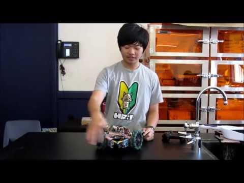
I have finally completed my omni directional robot. It took 5 weeks, days of coding, hours of wiring and 2 fires, but I’m finally done. I am very happy with the way it turned out and hope to improve it in the future. My main tips for those who want to build this are to keep calm and be smart. Don’t just plug things in, be safe and knowledgeable. Also try to study up on your trigonometry so you can write this code. Don’t get stressed out, it will take you a while to make, but in the end it ‘ll be worth it. I hope my videos are very knowledgeable and I teach people a thing or two.
Milestone 3: Basic movement and rotation
I finally got the robot to move in all directions. The only problem is the unstable nature of the controls. It may suddenly stop working or the robot may go crazy. I’ll need to look through the coding to troubleshoot this issue. The only thing that I have to do is to balance out the robots controls. The directional movement works, but not very well. There are still inherent problems with complex movements, such as northwest or southeast. This will most likely be solved by writing out a new code for the directional movement. The directional movement code is by far the most complex part of the code. It requires knowledge of both trigonometry and a lot of Geometry. There are many laws about angles that you will need to know, such as alternating interior angles, a straight line is 180 degrees etc.
http://www.youtube.com/hvyV0miT1Vc
Milestone 2: Rotational movement and jittering
As seen on the video, I got most of my robot down. The rotational movement works perfectly, but in terms of actual movement I have some more troubleshooting to do, as it is not perfect. The code for the directional movement is far more difficult than that of the rotational movement. In terms of the negative milestone, it’s very small. This will happen if it is powered by arduino, but can be fixed with an external power supply. If anyone wants to build a robot in the future, disregard the spazzing. It’s going to happen when you plug it in. It is an unavoidable problem. Just wait for your external power and all will be fine. I made the mistake of spending days worrying about this when it isn’t really something you need to worry about.
http://www.youtube.com/OYeIm2UHdmc
Milestone 1: Wiring my robot’s circuit board
Here is the wiring for my omnidirectional robot. In this video I explain all significant wires and parts in the circuit. I’ll explain what the important parts are needed for and also give tips on safety and required materials to complete your robot’s circuit. Here are some very important tips in making your circuit work.
– Put GND on a rail, every piece of electronic tech needs to go to GND, so make sure you have room for it.
-Make sure your current is properly controlled by using OHms law, V=I/R.
– Organize your wiring, try to use the least amount of wiring possible to stay organized.
-If there are any exposed wires, use heat shrink to cover them up. This will cause a short if the two touch, if this happens it can be potentially dangerous.
http://www.youtube.com/p6eg-baTNXg
Failed resistor placement
I began working on my omni directional robot right after i finished the light seeking robot. So far so good. I was able to hook up the servos and get them all to run, but I needed more power, so i decided to add an external power source. I decided to use a 7.2 Volt nickel cadmium battery I thought I got all of my wiring correct and the battery was ready to go…I was wrong.

You may be wondering what that is, well there are two problems with that picture. The first thing you might notice is the brown area on the right corner. This is not dirt, this is in fact the charred point of the breadboard. Electricity is dangerous business, and if you make small mistakes like me, you will start a fire. Luckily the fire was very small and only burned the jumper cable, also Nickel-Cadmium is not explosive. This fire could’ve easily been avoided if i placed my resistor correctly. The circle is the point in which i placed my wire.Don’t do this, avoid at all cost. By doing this the current goes directly to the wires because it’s on the exact same row as the other wires. Instead place it on a separate row, as indicated by the arrow. This would be the proper way to use a resistor. You are allowing the current to go through the resistor because it is separated from the other wires, you are not letting it go directly to the motors.
Aaron’s Light seeking Robot
http://www.youtube.com/PCkLNWCJ_9g
This is a lightseeking robot. There are many parts that each have their own function. The battery provides the entire machine with voltage.This voltage is activated with the press of the on switch. The voltage is sent to the transistors which amplify the power of the current because the current itself is not powerful enough to move the motor. There are also many resistors on the board that change the resistance on the circuit. The main factor in terms of resistance would be the photoresistors. The photoresistors an LDR, which means it’s a light dependent resistor. The resistance will become lower the more light there is. The photoresistor is very important because this is what makes it light seeking. It is directly connected to the motors, and the motors stop and change speed based on the resistance given off by the photoresistors. The trimmers are used to change certain factors in the light seeking robots. Such as LDR sensitivity and the overall motor speed. The electrolytic capacitor is the final part. It is used to filter electricity and store small amounts of it. It can be a small source of current, similar to a battery.
There were many problems that arose with this robot. One small mistake led to another and eventually set me back an entire day. The first major problem was a wiring problem. When the soldering iron is too hot and overheats the board, the copper can strip. When this happens there is no longer a connection. To fix this you must make a direct contact between two points by either soldering a wire between two soldering points, or stripping the solder mask and directly soldering a wire to the copper underneath. The disconnections were the main issue. The most common problems were problems with transistors. Since transistor 1 was connected to the left side, the entire left side didn’t work, as transistors are needed to power the motors, so I needed to reconnect it manually. After I reconnected transistor 1 the robot began to work again.
Reflections
Towards the end of BSE my level of energy was not the same as it was in the beginning, I was getting more and more tired, but my level of motivation was only getting higher. After Weeks of building, days of coding, hours of wiring and 2 fires, I’m done with my robot. If I were to give any tips to future BSE students it would be, don’t be afraid to ask for help. Try solving the problem on your own, but sitting for hours confused is not going to get anything done. Over the 6 weeks I learned a lot about myself and what I enjoy doing. I learned how much I needed to improve my math skills and also learned how much I needed to work on my coding, but at the same time I learned that I loved putting things together and making things work. I learned that frustration and engineering come in a pair. You will be so frustrated, and so tired, but in the end it will be worth it. In the end it’s not what you know, but how hard you try. I’m very happy with the way that my 3 wheel omni directional robot turned out. It’s not perfect, but it works in a way that I enjoy. I feel like BSE didn’t just leave me with a robot, but more importantly, it left me with knowledge. Knowledge about myself and knowledge about engineering. I am glad I joined this program and hope others take advantage of this great opportunity.