Line Following Robot
Engineer
Aditya S
Area of Interest
Mechanical Engineering
School
Gunn High School
Grade
Incoming Junior
Here’s the link to my build plan: https://docs.google.com/document/d/1vxi-tRaLMpc8ZcZ6oC3vmmtifSlqMfxgjFxJDYox_Tc/edit
FINAL MILESTONE/ DEMO NIGHT
My final milestone was to code the robot so that the motors would respond to the IR sensor values. Basically, the robot would go straight if both IR sensors were on black, and stop if both sensors were on white. If the left sensor was on black and the right sensor was on white, then the robot would turn right, and vice versa. The robot worked several times on my track, but before demo night the power went out of the battery. My experience at Bluestamp was really memorable and eventful, if a little frustrating at times. I learnt a lot of things I never thought I could learn in two weeks, such as basic electrical engineering and Arduino coding. This also includes information about the IR proximity sensors, motor drivers, and hardware components regarding my project, and the solutions to their accompanying hardware problems. I also learnt important skills like soldering, planning, and documentation. I will never forget this exciting experience and it really made a difference in my interest in engineering because it tested my resolve and determination in problem-solving.
//defining pins and variables
//Motor A connections
int enA = 9;
int in1 = 8;
int in2 = 7;
// Motor B connections
int enB = 3;
int in3 = 4;
int in4 = 2;
void setup() {
//declaring pin types
pinMode(A4,INPUT);
pinMode(A5,INPUT);
pinMode(enB, OUTPUT);
pinMode(in3, OUTPUT);
pinMode(in4, OUTPUT);
pinMode(enA, OUTPUT);
pinMode(in1, OUTPUT);
pinMode(in2, OUTPUT);
//begin serial communication
Serial.begin(9600);
}
void loop(){
//printing values of the sensors to the serial monitor
delay(1000);
Serial.print(“IRSensorip “);
Serial.println(analogRead(A4));
delay(1000);
Serial.print(“IRSensorip2 “);
Serial.println(analogRead(A5));
//establishing motor speeds
analogWrite(enA, 135);
analogWrite(enB, 150);
//line detected by both
if(analogRead(A4)>950 && analogRead(A5)<407);
{
//Forward
digitalWrite(in1, HIGH);
digitalWrite(in2, LOW);
digitalWrite(in3, HIGH);
digitalWrite(in4, LOW);
}
//line detected by left sensor
if (analogRead(A4)<950 && analog2Read(A5)<407);
{
//turn left
digitalWrite(in1, HIGH);
digitalWrite(in2, LOW);
digitalWrite(in3, LOW);
digitalWrite(in4, HIGH);
}
//line detected by right sensor
if(analogRead(A4)>950 && analogRead(A5)>407);
{
//turn right
digitalWrite(in1, LOW);
digitalWrite(in2, HIGH);
digitalWrite(in3, HIGH);
digitalWrite(in4, LOW);
}
//line detected by none
if(analogRead(A4)>950 && analogRead(A5)>407);
{
//stop
digitalWrite(in1, LOW);
digitalWrite(in2, LOW);
digitalWrite(in3, LOW);
digitalWrite(in4, LOW);
}
}
SECOND MILESTONE
My second milestone for the Line Following Robot is to give the IR proximity sensors the ability to record their measurements in the serial monitor. First, I wired up the IR sensors to the GND and 5V rows in the breadboard and hooked up the output pins to the Arduino board. Then I cut two pieces of wood, created a T-brace so that it could be used a mount for the IR sensors, and attached it to the robot. Finally, I coded the program such that when the IR sensors picked up a value, it would get printed in the serial monitor.
void setup()
{
// put your setup code here, to run once:
pinMode(A4,INPUT);
pinMode(A5,INPUT);
Serial.begin(9600);
}
void loop()
{
// put your main code here, to run repeatedly:
Serial.print(“IRSensorip “);
Serial.println(analogRead(A4)); //Threshold:950, White<950, Black>950
Serial.print(“IRSensorip2 “);
Serial.println(analogRead(A5)); //Threshold:417, White>417, Black<417
delay(250);
}
FIRST MILESTONE
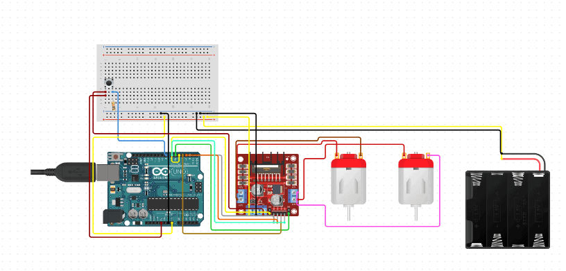
My first milestone for the Line Following Robot is to make both the motors reverse their rotational direction at the push of a button. To make this work, I built the robot’s chassis, attaching 2 DC motors, wheels, and a battery pack to the acrylic. I then loosely attached an Arduino board, breadboard and motor driver to control the motors and make the wiring easier and more spacious. I connected the (+) and (-) wires from the battery pack to a switch and the GND port in the motor driver, respectively. (I also connected the GND in the motor driver to the GND in the Arduino). I then connected (+) and (-) wires to the motor ports and soldered them to the motors. Finally, I connected the IN1-4 pins to the Arduino to control the direction of the motors. Using the breadboard, I wired the button and a 330Ω resistor to complete the circuit and control the direction of the motors.
int in1=8;
int in2=7;
int in3=4;
int in4=2;
int button=12;
int rotDirection=0;
boolean pressed=false;
void setup()
{
Serial.begin (9600);
// put your setup code here, to run once:
pinMode(in1, OUTPUT);
pinMode(in2, OUTPUT);
pinMode(in3, OUTPUT);
pinMode(in4, OUTPUT);
pinMode(button, INPUT);
}
void loop() {
// put your main code here, to run repeatedly:
Serial.print (digitalRead(button));
if (digitalRead(button) == true)
{
pressed = !pressed;
}
while (digitalRead(button) == true);
delay(20);
// If button is pressed – change rotation direction
if (pressed == true && rotDirection == 0)
{
digitalWrite(in1, HIGH);
digitalWrite(in2, LOW);
digitalWrite(in3, HIGH);
digitalWrite(in4, LOW);
rotDirection = 1;
delay(20);
}
// If button is pressed – change rotation direction
if (pressed == false && rotDirection == 1)
{
digitalWrite(in1, LOW);
digitalWrite(in2, HIGH);
digitalWrite(in3, LOW);
digitalWrite(in4, HIGH);
rotDirection = 0;
delay(20);
}
}


