Robotic Arm with Claw
My project is a robotic arm with a claw. Each of the joints in the arm has a servo that can be controlled remotely with a potentiometer.
Engineer
Noah M
Area of Interest
Computer Programming and Robotics
School
Brooklyn Technical High School
Grade
Rising Junior
Reflection
Seeing my robotic arm work as well as it does makes me appreciate how far I have come since I started the BlueStamp program. It represents not only the effort I put in, but also everything I learned in the building process. I began with very little knowledge of Arduino, potentiometers, NRF24L01 modules, breadboards, and countless other things that are in my finished project. Now, I am so familiar with all the components of my project that I could build my robotic arm a second time.
I also appreciate how my writing improved because of my documentation. I never had any experience with writing in the engineering field starting the program. I learned how to express my ideas clearly and in an organized manner. This is a skill that I will be using for the rest of my STEM career.
If I had more time to make modifications, I would add a chassis and wheels to my arm so that it could move around. This is something that I would have fun making and that would also be a new opportunity for me to learn more. It would open the door to learning about motors and other parts of vehicles. I am very proud of what I have built and am excited about my STEM education going forward.
Final Milestone
How it works
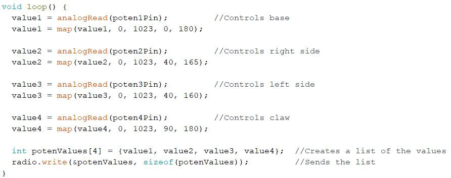
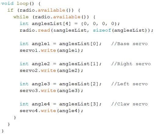
The mechanical structure of the arm provides locations for servos at each of its four joints. This allows control over four different ranges of motion. One servo controls the base, one controls movement forwards and backwards, one controls movement up and down, and the last controls the opening and closing of the claw. Each of the servos receives a value from a different potentiometer, meaning that the NRF24L01 transceivers are communicating four distinct values. Instead of sending an integer value for each of the potentiometer values, I created an array, or a list, that holds all of the integer values. After the Arduino Nano transmits the array, the Arduino Uno receives the array and writes each index onto a specific servo. This process is looped so that the positions of the servos are constantly being updated. I created a circuit that supplies five volts to all of the servos, which is enough power to ensure the arm functions properly.
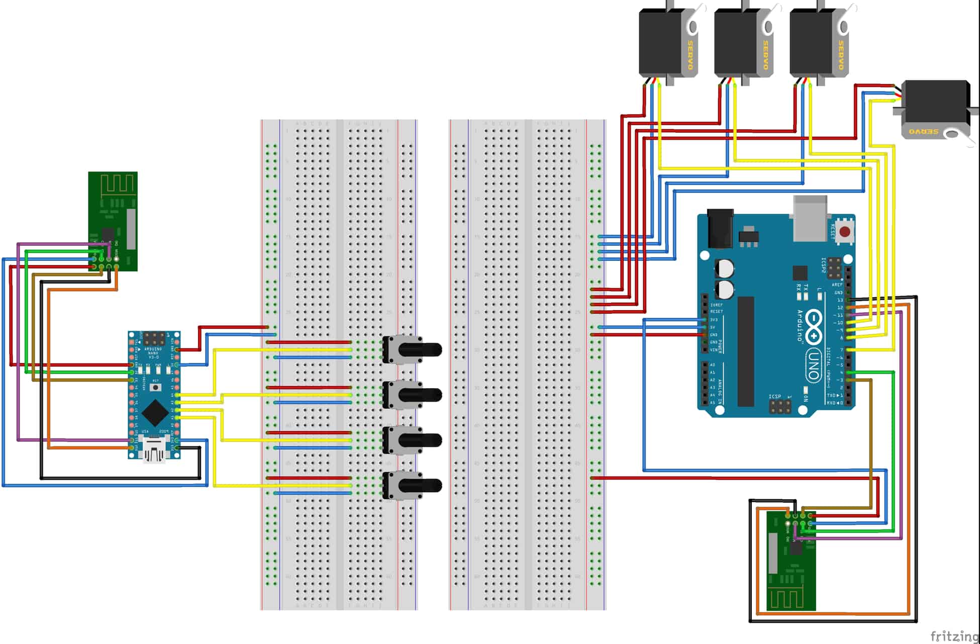
I started working towards this milestone by building the mechanical structure of the arm. The kit included four servos, though mid-construction I found that one was broken and had to be replaced. After that, I added three more potentiometers to the Arduino Nano’s circuit and made sure that all four potentiometers reported a value. Next, I created the variable that stores a list of all the potentiometer values. I programmed the transceiver in the Nano’s circuit to transmit it to the transceiver in the Uno’s circuit. I then coded the Arduino Uno to write each index onto a corresponding servo. Finally, I attached the arduino board and breadboard power strips to the robotic arm’s platform. I also rewired the servos’ circuit to make it more organized. For a wiring diagram of the final circuits, see figure 1.
I finished my project! For my final milestone, I completed the robotic arm by building the mechanical structure, attaching the servos, and adding potentiometers to remotely control their movements. I also put the Arduino Uno microcontroller and the breadboard power strips on the arm’s platform so it was more compact. Pictures of the completed arm can be seen in the slideshow to the left.
Reflection
Most of what I learned in this milestone related to increasing the scale of the project. I learned how to introduce more elements into my circuits without interfering with what I previously made. I also learned how to declare variables as an “array” type and how to add integer variables to arrays. The arm’s assembly kit is created by Microbotlabs.
Second Milestone

How it works
The process in which the potentiometer controlled the servo remained virtually unchanged. The only difference was recording the value the potentiometer reports in one circuit and sending that value wirelessly to another circuit with the servo. Also, I realized a mistake I made with my first milestone. I accidentally connected two pins of the potentiometer incorrectly. This was the reason the potentiometer’s value changed exponentially.
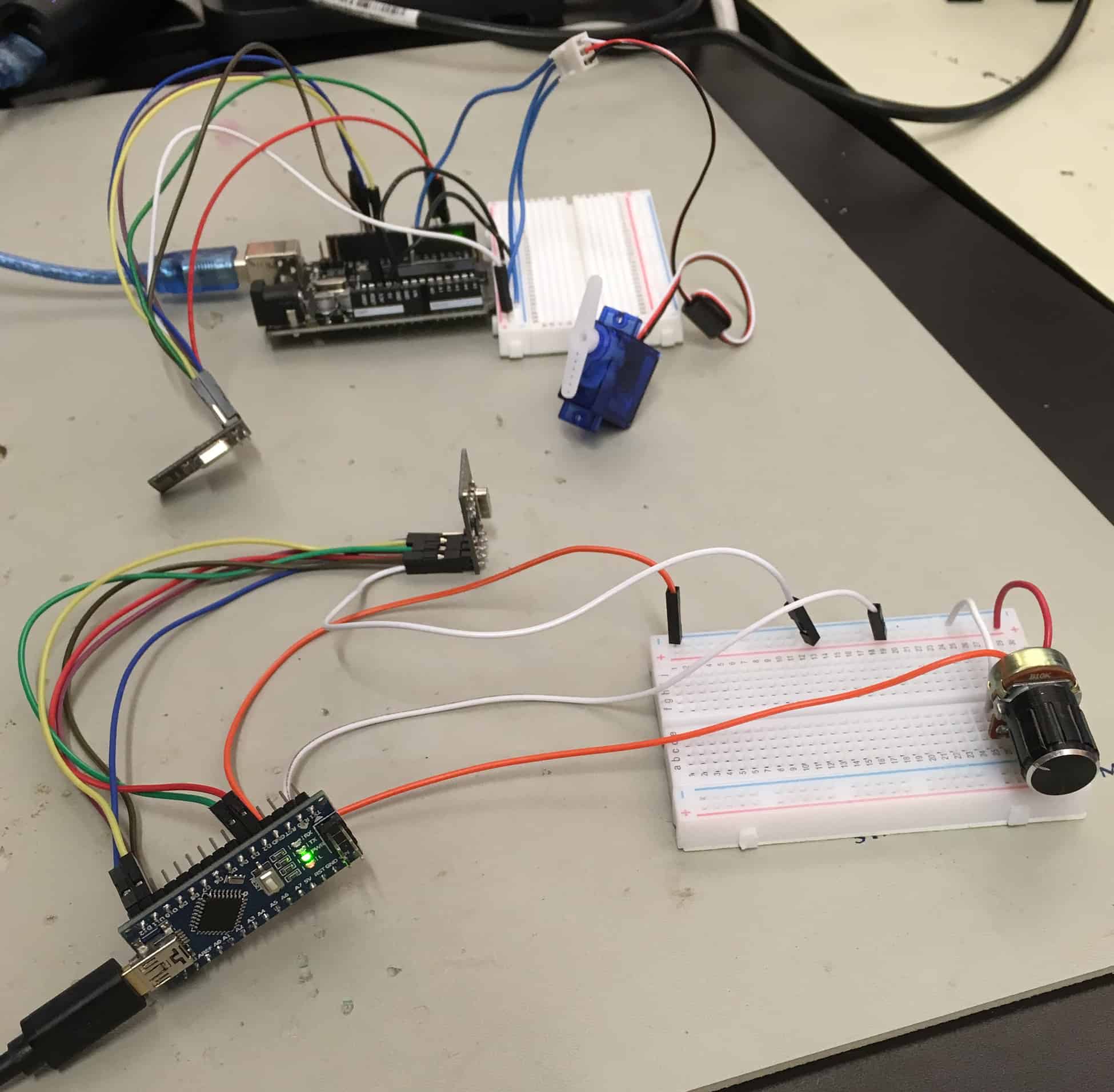
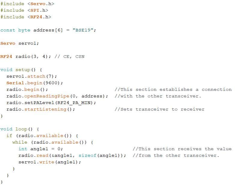
To add the NRF24H01 transceivers to the Arduino, I wired each pin on the transceiver to its corresponding pin on the Arduino microcontroller. I connected the power pin on the transceiver to the 3.3V pin on the Arduino microcontroller. I also connected the ground pin on the transceiver to the ground pin on the Arduino microcontroller. The CE, CSN, MOSI, MISO, and SCK pins all deal with SPI (Serial Peripheral Interface) communications, or communications between with the Arduino microcontroller and itself. The CE (Circuit Enable) pin is used to communicate if the transceiver is active and whether it is transmitting or receiving. CE can connect to any digital pin on the Arduino microcontroller; on the Arduino Uno it is on 3 and on the Nano it is on 2. The CSN (Chip Select Not) pin identifies which chip the transceiver communicates with and, like the CE pin, can connect to any digital pin. On the Uno, it connects to 4 and on the Nano, it is on 3. The MOSI (Master Output Slave Input) pin is for when the microcontroller sends data to the transceiver, and has to be connected to pin 11. The MISO (Master Input Slave Output) pin is the opposite: It handles communication from the transceiver to the microcontroller, and goes to pin 12. Finally, the SCK (Serial Clock) pin is for establishing the rate at which data is sent between the transceiver and microcontroller, and connects to pin 13. For full wiring, refer to figure 1. After I wired my project, I created two separate program scripts, one for the Arduino Uno and one for the Nano. In the Nano’s script, the potentiometer’s reported value is transmitted, and in the Uno’s script, the value is received and written onto the servo.
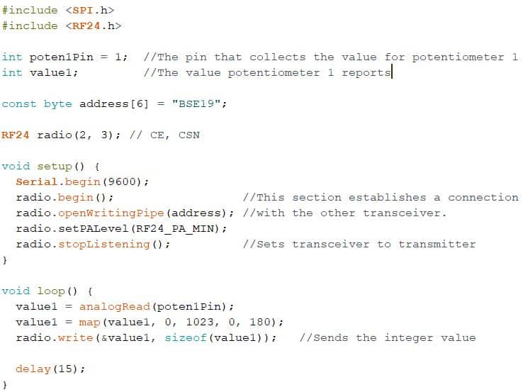
For my second milestone, I controlled a servo with a potentiometer remotely through Bluetooth. Figure 2 shows both of the completed circuits. I used an Arduino Uno in the servo’s circuit, and an Arduino Nano in the potentiometer’s circuit. I added an NRF24H01 transceiver in both circuits so that they could communicate with each other.
Reflection
To implement the Bluetooth transceivers, I learned how the NRF24H01 modules worked, and the purposes of each of the pins. Because I created an entirely separate circuit, I familiarized myself with the Arduino Nano, as I had exclusively been using the Arduino Uno before. I also learned how to program each of the transceivers to communicate with each other. The NRF24L01 datasheet can be found here.
First Milestone
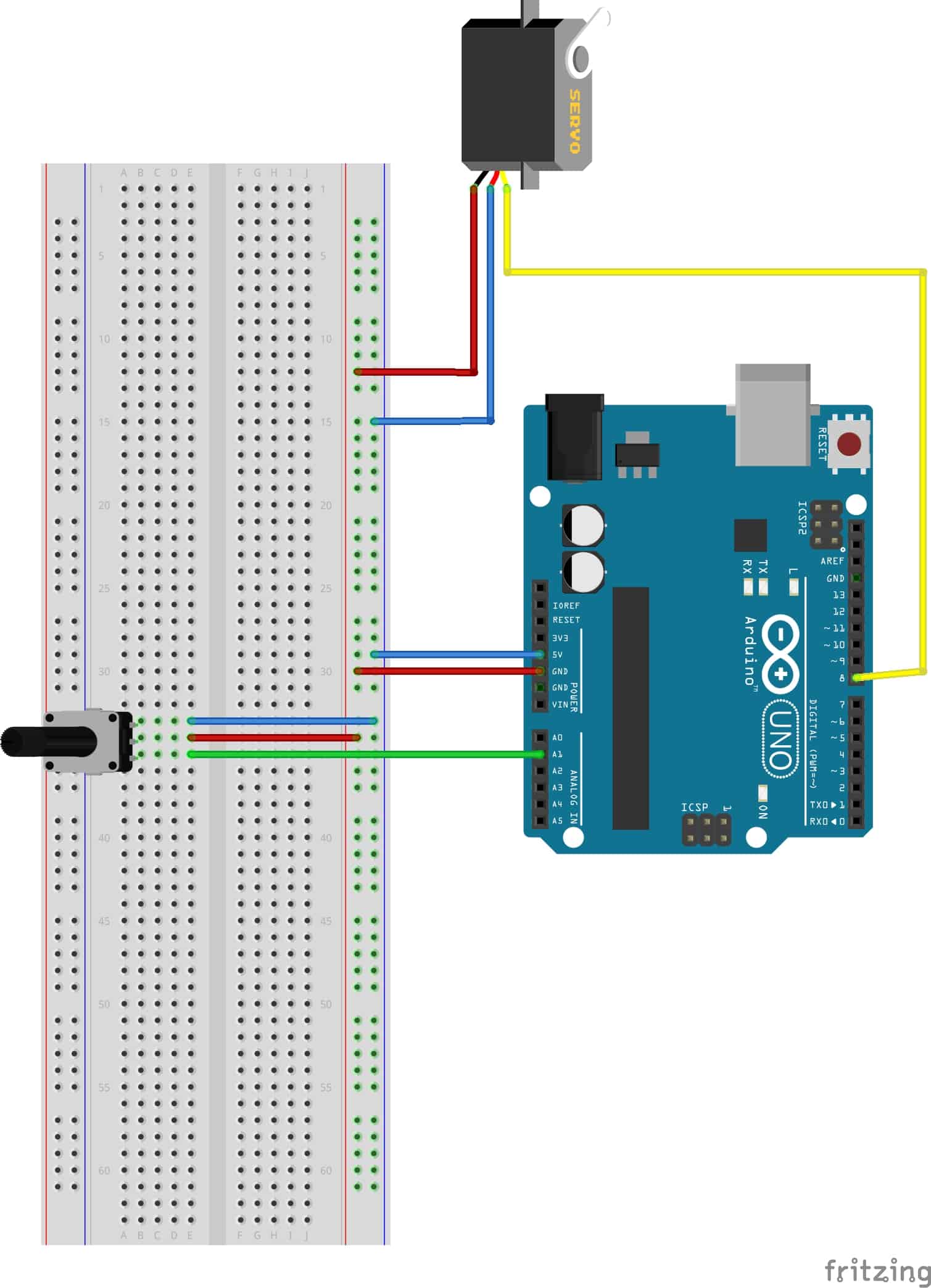
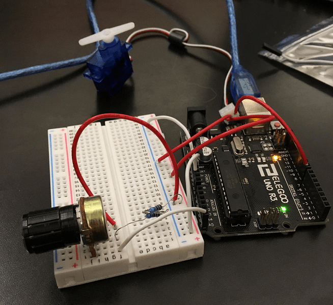
My first milestone was to control a servo with a potentiometer. It was important to make the controls smooth—I wanted the servo to rotate at a constant speed when the potentiometer was turned. See figure 1 for the completed circuit.

How it works
The potentiometer is a variable resistor. When a current flows through it, the potentiometer provides a resistance that can be controlled with a knob. The stronger the resistance is, the lower the voltage is coming out of the circuit. In figure 2, if Z1 represents the potentiometer, Vout can be controlled. This is significant because the potentiometer reports a value based off Vout on a 0 to 1023 scale. The minimum value represents the minimum Vout the potentiometer can allow and the maximum value represents the maximum Vout the potentiometer can allow. This value is mapped onto a 0 to 180 scale. I write this value onto the servo, meaning the servo has a 180 degree range of motion. For full wiring, see figure 3.

Reflection
To get to the first milestone, I learned how to use Arduino and to program in the Arduino IDE. Additionally, I had to learn how to read and record values reported by a potentiometer. I also became more proficient with circuitry and wiring. For example, I needed to create a circuit involving both the potentiometer and the servo, so I needed to learn how to incorporate a breadboard into my project.
I encountered a problem when I first connected the servo to the potentiometer. The potentiometer rotated the servo, but the rate at which it did it changed exponentially depending on the position of the servo. To solve this problem, I needed to add resistors in the circuit after the potentiometer so that the values reported by the potentiometer changed at a more linear rate.
Starter Project
My starter project is the Useless Machine. It is a black box that features a toggle switch on the top. When flicked, an arm emerges from a hatch on the top, flicks the switch back to its original position, and then recedes back into the box. Images for my completed project and the internal components can be found in the slideshow to the right.
How it works
The switch on the top is connected to an electric circuit inside the box. Flicking it activates a motor connected to an arm, causing the arm to continuously rotate upwards. It rotates upwards until it opens the hatch and hits the switch back to its original position. This switches the polarity of the voltage, reversing the direction of the current through the motor. This causes the arm to start rotating in the opposite direction. The arm rotates downwards until it activates an internal switch. This opens the circuit, turning the motor off. For circuit diagram photos, see the slideshow to the left (Images source: http://frivolousengineering.com/uselessmachineexplained.htm).
Reflection
Over the course of the machine’s construction, I learned some technical skills, such as soldering, and also improved on many of the technical skills I had knowledge of when I started building. The project was largely electrical and mechanical, so I was often using drills, screwdrivers, a soldering iron, and other tools. I also learned methods to identify a problem. When I first finished the base design, I found that the arm was not moving at all. To solve this, I first tried to locate the source of the problem. I checked the wires connecting the batteries, the motor, and the PCB (Printed Circuit-Board). Then, when I looked at the PCB, I tested each component one by one. After testing the resistors and the LED, I found that the circuit was open as a result of insufficient solder at the screw terminal, the place where the wires connect to. I used a multimeter to test voltage in the specific areas I checked for problems. Going forward, I can check for problems in my future projects using the same or similar methods and tools that I used to check for the problem in this project. The Useless Machine kit was created by Spikenzielabs.


