NeoPixel Lightsaber
Engineer
Sean B
Area of Interest
Toy Design/Mechanical Engineering
School
Mamaroneck High School
Grade
Rising Sophomore
Starter Project
My Starter Project is the Electronic Dice Kit, which recreates the function of a real die by showing a number from one to six whenever it senses impact, mainly from dropping it. I enjoyed this project because it helped me learn and practice soldering skills, and taught me about its different components.
Demonstration
How it works
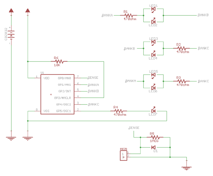
The kit’s main components are a 3V battery, Piezo sensor, a PCB, a PIC microcontroller, one diode, six resistors of varying types, and seven LED’s. The Piezo sensor uses what is called the Piezoelectric effect to sense when the die is dropped. The Piezoelectric effect is when an electric pulse is sent out in response to pressure. The Piezo senses when it is dropped, and sends a current to the Microcontroller to display the numbers. It does this through the PCB, or Printed Control Board, which is where all the pieces are soldered to connect them together. In order to connect a component to the PCB, you solder its leads to one of the exposed pads, and the solder serves as the adhesive and electrical connection. For my project, this was also the place where I screwed the acrylic base for the Piezo. All of the components were soldered onto this board. The PIC chip, which receives the current from the Piezo, is a microcontroller, which is a tiny, self-contained computer that controls the other components on the PCB. This specific PIC can also enter sleep mode, which is activated to help conserve power when the die is not being used. Sleep mode is on a timer that resets after every move, so it won’t turn off during use. The microcontroller receives the current in the form of a value that gets translated into a number from one to six. It then sends a current to tell the LED’s which number to display. The diodes and resistors help to control the flow of this current, the diode allowing it only to go in one direction while the resistors resist the flow in order to slow it down. The current finally reaches the LED’s, or Light Emitting Diodes, which are pretty self-explanatory. They receive the current and display the number, turning off when given the command for sleep mode. I faced a few challenges with this project, namely soldering and making sure I had the right pieces going in the right places. Overall, I had a lot of fun with this project and am glad I was able to complete it.


