IR Line Following Car
The IR Line Following Car is a RC car retrofitted with two IR sensors to detect and follow a line. The car is also implemented with various modes such as a regular remote control mode and an obstacle avoidance mode.
Files: https://github.com/T3rry-W/BSE2019.git
Engineer
Terry W
Area of Interest
Mechanical Engineering and Computer Science
School
Bellarmine College Preparatory
Grade
Rising Sophomore
Reflection
Overall, I would say my experience at BlueStamp was awesome, and couldn’t have been better. BlueStamp taught me to improve my time management, as I had to effectively manage my time throughout the six weeks. BlueStamp also taught me to improve my work ethic, such as organizing all my parts, and working efficiently. The mentors really pushed me to learn on my own. I had a lot of fun learning about various electronic components, interacting with my peers, and making new friends along the way. I would definitely like to thank my mentors in the room, Asher, Rish, Skye, and Eduardo. Couldn’t have done it without them!
Third Milestone: Remote Control
For my third milestone, I decided to make a remote control for my car. A lot of my time and effort was spent on learning/figuring out how to make the two NRFs communicate between each other, and trying to solder all my connections.
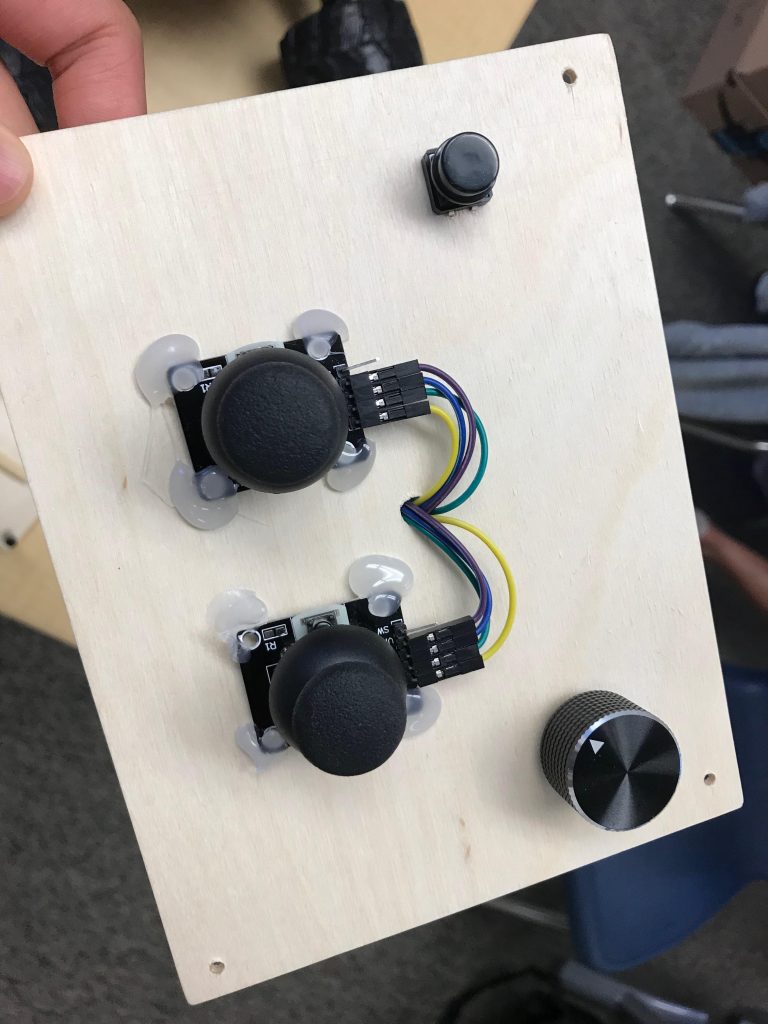
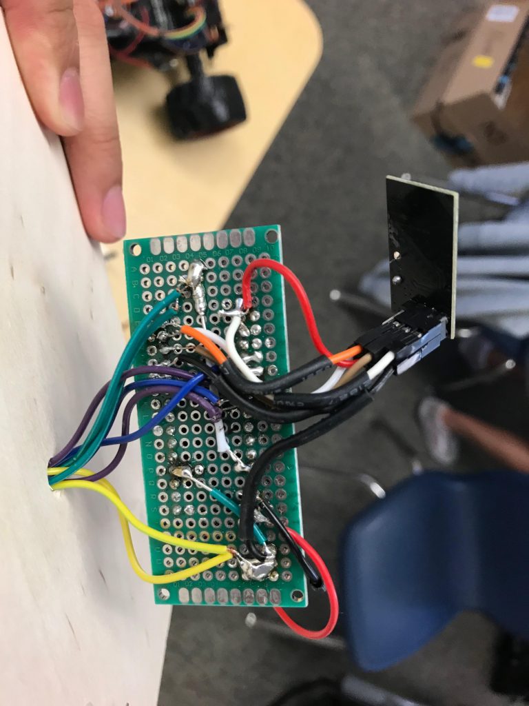
How it Works
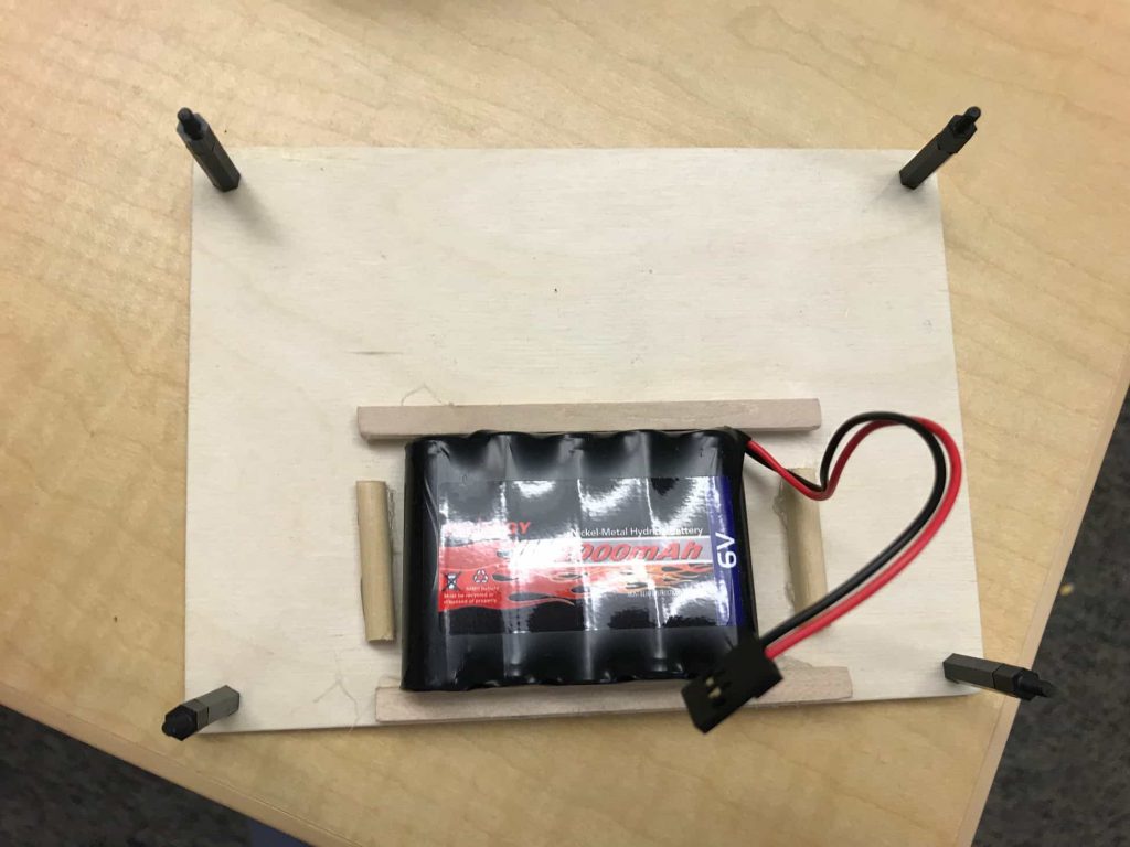
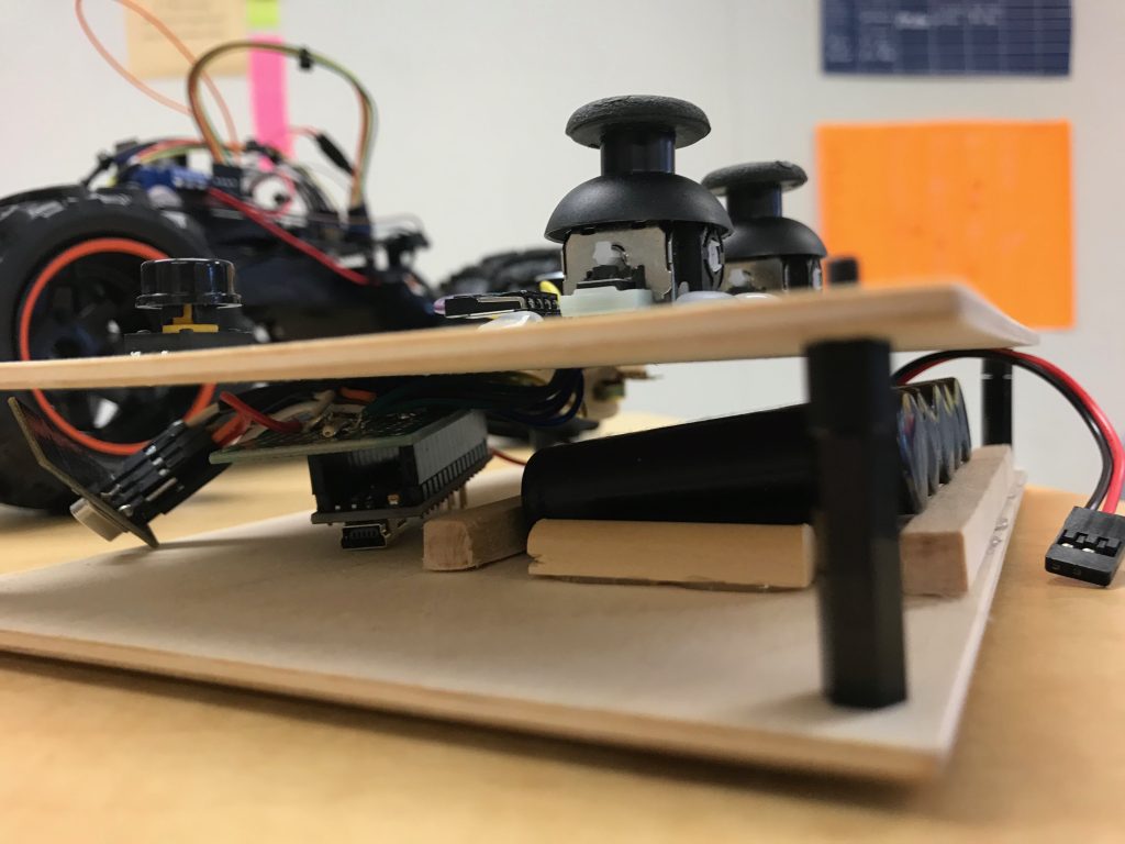
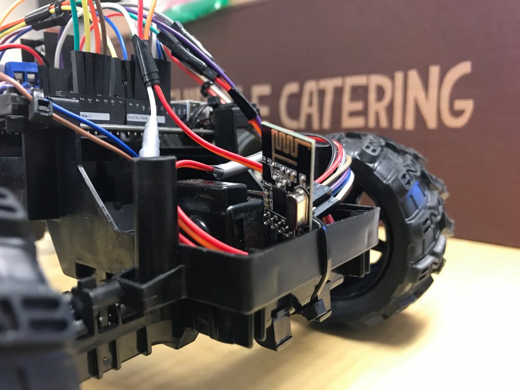
My remote control mode is made up of an Arduino Nano, two NRFs, and two joysticks. The two joysticks are soldered to the Nano, and to one nRF. The other nRF is on my car, wired to my Arduino Uno. The two joysticks provide analog data through two potentiometers, one on the x-axis, and one on the y-axis.
Second Milestone: Line Following
For my second milestone, I decided that I would get the line following to work. I spent a bit of time figuring what method I would use. I did eventually figure it out, but ran into a second challenge, fine tuning my car’s movement. My car has a very wide turning radius, so I had to make many trial runs, and determine the appropriate speed for the car.
How it works
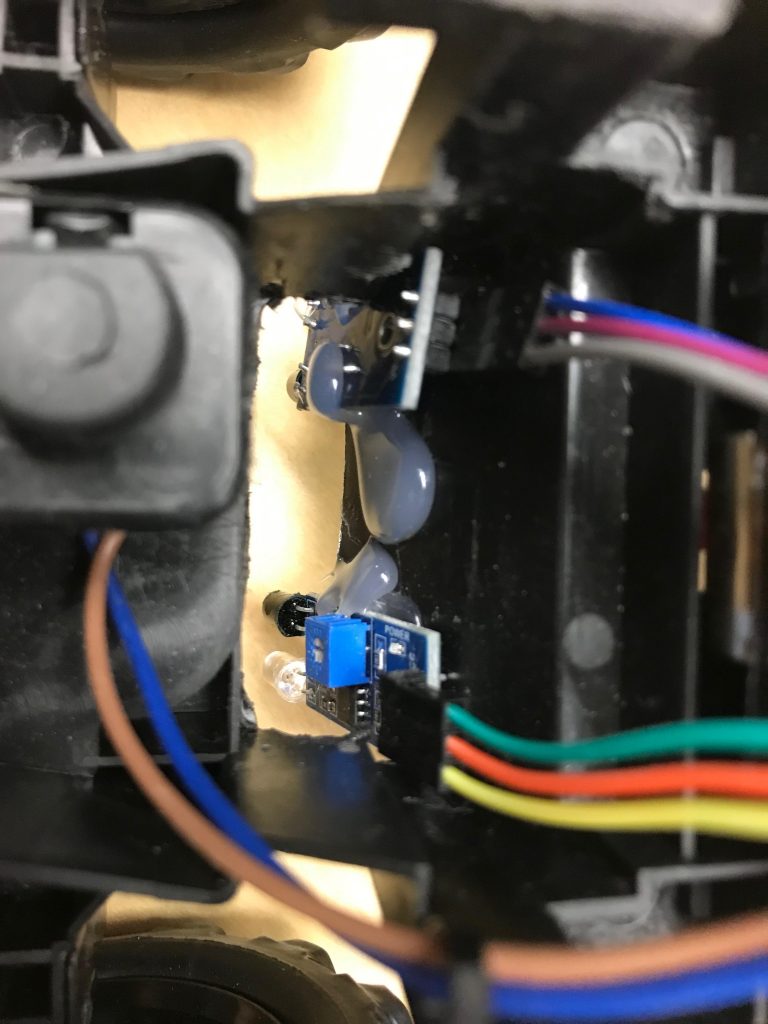
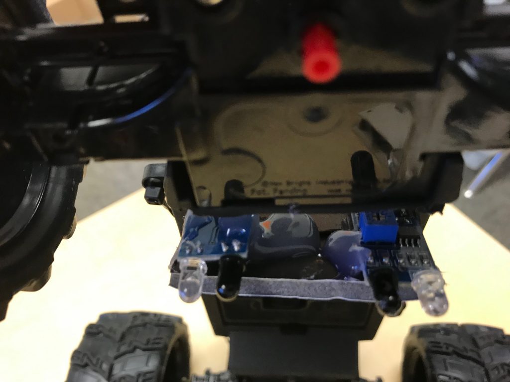
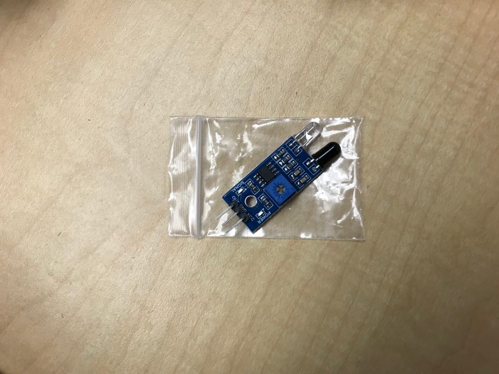
For my line following mode, I used two infrared (IR) sensors. The two IR sensors are mounted on the bottom of my car. The two sensors detect the edge of the black line it follows, and uses a method known as edge detection. If the edge of the line is detected, the car moves/turns in that specific direction.
First Milestone: Motor Control
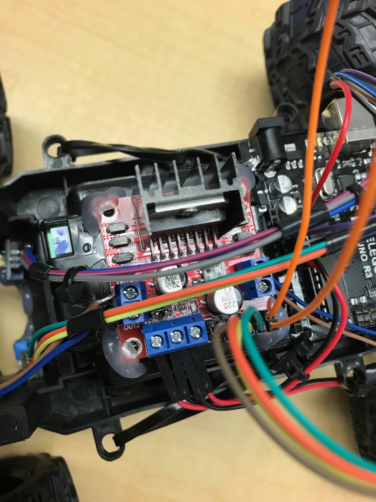
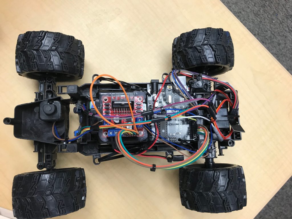
For my first milestone, I decided that gaining control of both motors would be adequate. I began by removing all of the components from the car except for the stock PCB, the motors, and the drive base. I then began analyzing my PCB, and determining whether or not it would be essential to my project. After some planning, I concluded that I would not need the PCB. I went ahead and hot glued my motor driver (SparkFun L928N) onto my drive base, and began wiring some motors. After determining the proper connections needed, I stripped, tinned, and connected my motor wires to the motor driver. I then attached jumper cables from the motor driver to the Arduino, as well as jumper cables for power. The biggest challenge I faced during my first milestone was perfecting my steering mechanism. The steering was driven by a DC motor, which I found impractical. I did a lot of testing with the motor and my code, to determine the exact speed and timing needed to turn my car. In the end, after a few days of testing, I finally found the appropriate timing and speed for my motor.
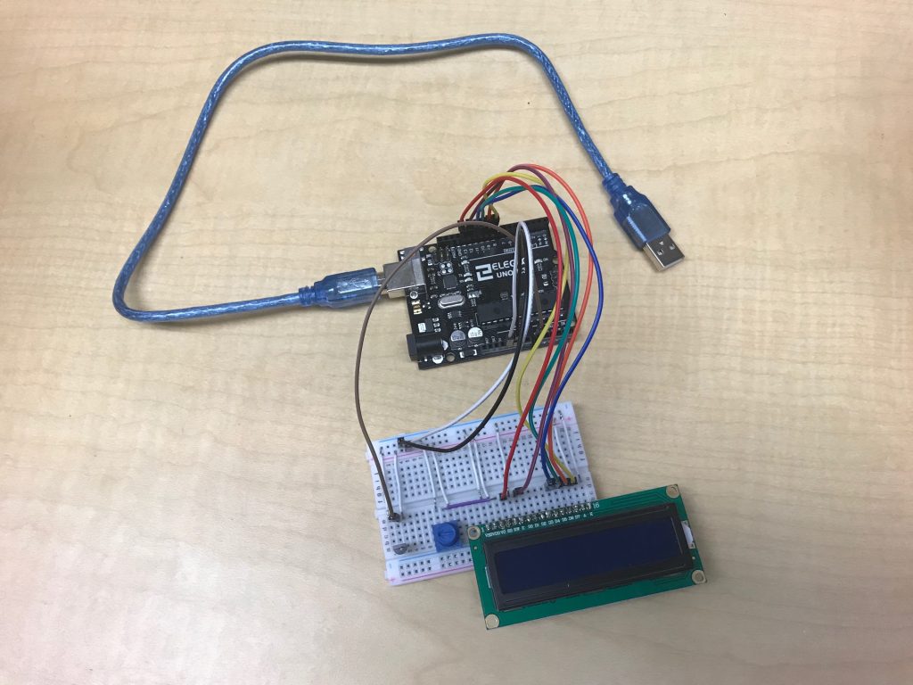
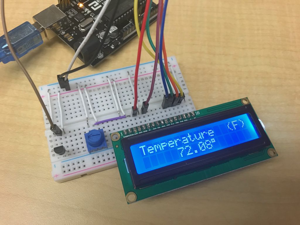
Starter Project: Temperature Sensor Display
How it Works
The entire project consists of the following components: an Arduino Uno, a mini breadboard, jumper wires, a potentiometer, a temperature sensor, and a LCD (liquid crystal display). The core component of the entire project is the temperature sensor. The sensor works by changing its voltage output, proportionally to the change in temperature. The Arduino then reads the analog signal, and through a series of equations, converts it into a digital signal, and displays it on the LCD.