Reflection
Method
-
Controlled by flex sensors
Control the servos and motors with flex sensors on the same circuit.
-
Wireless connection
Communication with radio transmission via the NRF modules.
-
Car chassis and glove
Fit each device with all of the proper components.
Final Milestone
void E() {

//clawopen

while (data.text == 69 && pos <= 90) {

pos=pos+30;

myservo1.write(pos);

myRadio.read( &data, sizeof(data));

}

}
The way I controlled the servo was by incrementing its position by 30° each time the loop was run. I set a minimum position for the function that decreased the position and a maximum for the function that increased the position since that is the range the servo can move in to control the servo in the claw mechanism. Anything more extreme might break it.
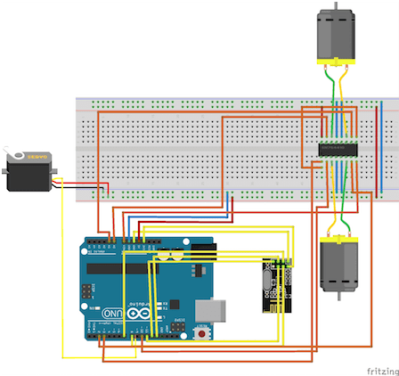
Car Schematic
void E() {
//clawopen
while (data.text == 69 && pos <= 90) {
pos=pos+30;
myservo1.write(pos);
myRadio.read( &data, sizeof(data));
}
}


Second Milestone


const byte interruptPin = 2;

void setup() {

pinMode(interruptPin, INPUT);

attachInterrupt(digitalPinToInterrupt(interruptPin), blink, RISING);

}
This change in input is the press of a button and change in state for the LED. I also wrote functions that interpreted different gestures, considering the mode, to send a unique character to the receiving NRF. This would allow the other Arduino to interpret the characters and cause certain movements from either the car or the claw.
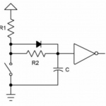
One of my main issues for this milestone was inconsistency with the button. For my purposes, bouncing is the tendency of a button to generate multiple signals as it opens or closes a circuit. It is a mechanical part that bounces up and down. This leads to confusion when the Arduino has to determine if the button has been pushed. Debouncing is a method of ensuring that only a single signal will be sent at a time, with no fluctuation. To debounce my circuit, I used a .001 µF 50V capacitor, which functioned to store charge until it releases it all at once, effectively sending one signal at a time. See Figure 2 for the general debouncing circuit used here.
const byte interruptPin = 2;
void setup() {
pinMode(interruptPin, INPUT);
attachInterrupt(digitalPinToInterrupt(interruptPin), blink, RISING);
}

First Milestone
val = map(average, 130, 350, 0, 180);
The readings for the flex sensor were very sporadic, so I wrote a for loop that averaged every 50 values to get a more constant data set.
val = map(average, 130, 350, 0, 180);
int flexpin = A0;

int val;

float average;

void loop() {

val = analogRead(flexpin)-454;

average=0;

for(int k=1; k<=50; k++){

average=average+analogRead(flexpin);

}

average=average/50;
int flexpin = A0;
int val;
float average;
void loop() {
val = analogRead(flexpin)-454;
average=0;
for(int k=1; k<=50; k++){
average=average+analogRead(flexpin);
}
average=average/50;
The Useless Machine