Reflection
BlueStamp has taught me some very important skills for engineering and life in general. Learning how to problem-solve and troubleshoot were very important in building my project and are useful skills for many fields. Each issue I encountered was somewhat frustrating but also valuable as I took many steps to resolve it. Also, taking the time to write and record my different milestones taught me the value of documentation. Documentation is helpful for both me and others who wish to build the same project. We also heard from many guest speakers, including entrepreneurs and innovators, who are a great source of inspiration for various paths I might choose to pursue in the future.
Final Milestone
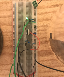
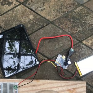
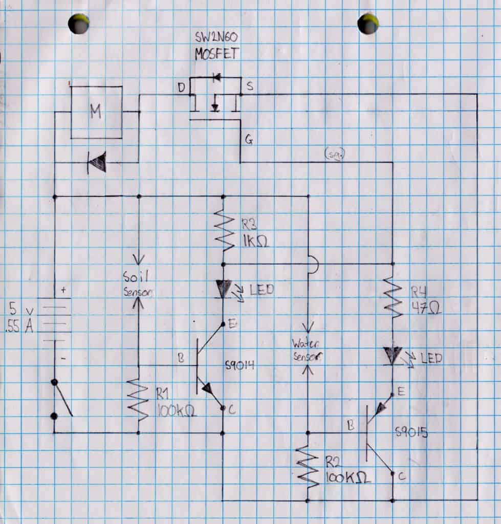
For my final milestone, I finished building the circuit and attaching the pump. I attached the tubing to the water pump using a hot glue gun. I also tested it a few times to fix any leaks and make sure it is airtight. I decided to use the breadboard for the final circuit. Using the perfboard was very difficult for this circuit because of the amount of close connections. I tested each connection using the continuity tester on a multimeter. Some connections were too close and current was flowing through parts it shouldn’t, causing the pump to always be on. I tried building the circuit more spaced out on a new perfboard but the pump also would not turn off when the soil was wet. Therefore, I went back to using the breadboard because it is easier to move the connections around and test if the circuit is working properly. Now the pump works properly and turns off when the soil is wet. I cut a wooden board to attach to the containers and breadboard. I also modified the project to be able to use solar power instead of a normal 5V power supply. To do this, I hooked up a 3.7V/4.2V Lithium Ion Polymer battery to a Lithium Ion Polymer charger. The Lithium Ion Polymer charger includes one capacitor to help store the charge. It can also be connected to a 6V solar panel to draw energy from the sun. Since the Lithium Ion Polymer battery provides around 4V to the circuit and the solar panel up to 6V so there will never be a shortage of electrical energy. When it is dark out, a power supply can be plugged directly into the charger’s DC jack to power the device. While building this project, I learned the importance of trial and error through adjusting and testing the circuit many times to get it to work. The more careful you are while building the circuit, the less troubleshooting and fixing will be necessary so take your time.


